Sir Michaelf30 . . . . . . .
Looks like you got about 4 years of use of this unit.
Somewhere between absolutely nothing and nil is being available for any service info from this units
designated Shindigen manufacturer.
They second source to multi distributors / brands . . . thats even including Wally World.
They want to Sellee Sellee . . . . . . . . . . . but alas . . . . . .no want you to Fixee Fixee.
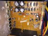
What my Sharp Eagle Beagle eyes are seeing, would be two warmed ? up spots on the board at the
inclusively marked up RED RECTANGLES.
Nothing thermally relevant is being seen on this side of the board, is there a possibility that hot components
are mounted at those spots on the other side of the board ?
At the extreme left of the board are lined up all of the U1 through U7 POWER OUTPUT INTEGRATED CIRCUITS
MODULES for the five POWER AUDIO output portions of this unit.
The YELLOW STAR marked units are probably being related to feeding the rear spatial speakers.
Can you pass on to us, their identification markings, placed on the sides of their cases.
The FUCHSIA STAR marked units seem to be receiving a bit of a differrent treatment, in respect to their
adjunct ancillary electrolytic capacitors.
Therefore, can you release the compressive bar with the GRAY RECTANGLE marked screws , to expose
those power unts identifications and pass back those to us also.
Just for information, the two ORANGE RECTANGULAR marked up areas are the +27 and -27 Volt power
supplies for all of those power amps.
Drop down to the top two BLUE RECTANGLE markups and you have the basic power supply for the bulk of the rest of the unit.
One supply line then drops down and then feeds into the top lead of that YELLOW RECTANGLE with its burnt 4.7 / or /.47 ohm resistor that has its bottom lead going down into the BLUE BOXED heatsinked regulator area.
Pass that heat sink mounted parts ID on to us also.
My RED STAR marked boxes at the very bottom must just be enclosing hidden / recessed input and output connections .
Initial metering will be done by having the set UNPOWERED and use of a DVM set in its ohms mode and set to its lowest ohms range and shorting the meter leads together to initially confirm your familiarity between a shorted connection . .which your meter will then display.
Then open the leads to confirm a non connective meter reading.
Then take the test leads and test across the 4 top fuses to confirm connected . . .intact . . .internal fuse links.
I feel sure that all 4 will be testing good.
Further info to be collected, would now require the use of a DVM in its AC mode and the unit powered up, in
order to get your weakened sound and then start at the very top right connector with its 5 connections of.
YELLOW---YELLOW---BLACK---BLUE---BLUE
Meter common negative goes to the center black connection and then meter between the two YELLOWs for their A.C. voltages and then the bottom two BLUES, with all of those voltages then being passed on to us.
Then go to the *yellowed* connector, just below, and use its top gnd connection to your meter black lead and
check for those marked voltages of 27 and 4 and 4. Expecting the 27 to be correct and DC, but that marked up two 4 Vs could be an AC voltage or possibly also AC if you change to metering only between the bottom 2 connections..
Drop down to the 3rd connector and go to AC metering mode and see if the meter Black is placed on one of the two black wires, that the two BLUE wire above, will show AC voltages being present.
Then at the 2 pin connector below I believe that meter probes can reach into half of the connectors 2 RED wire connections to acquire a final AC voltage across those two wires.Pass on that voltage.
Final reading will be between the cluster of 4 diodes just beside the last RED wire set tested . .ignoring the slightly spaced apart, sole diode, at their very top.
Use DC voltage test mode this time and use the LEFT side leads of either of the 3rd or 4th diodes up for being your your negative-black metering lead common and use the RED metering lead to test the voltage on the top of the earlier mentioned burnt resistor [ YELLOW BOX ]. Log down Voltage reading.
Then move the meter lead to the bottom lead of that resistor to see what voltage is getting through . . . . . . .if any.
Thasssssit . . . .now its doittoit . . .time.
YOUR MARK UP OF TECHNO REFERENCING:
73's de Edd