Ok, so first off let me tell you I am a complete newbie when it comes to electronics. AC is WAY beyond me but I do, somewhat, understand DC circuits. I installed my own stereo with an amp and two subwoofers when I was in high school. I also built the box for the woofers which I am much more inclined to do. Anyhow, I have started the journey into small electronics. My knowledge comes down to this: I just recently discovered that I can control direction of the flow! WHAT?!!!! A DIODE! Yes, my friends that is where I am... a lowly diode. That was the spark (pun intended) I needed to get me interested in the world of electricity. SO here it goes:
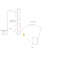
12V 5A AC/DC power supply (8 DC barrel plug connectors)
First DC Channel powers a Sonoff 4ch Wifi Switch
Second DC Channel I use a DC terminal barrel with (+) going to the NO side of the relay and the (-) to the NC side
To run the Pump I am required to tie CH 1 relay and CH 2 relay (+) and (-) together
So, CH 1 COM is now (+) and CH 2 COM is now (-)
I have run CH 2 COM (-) to a grounding bar
CH 1 COM (+) Lead...................................................................?
?............................................ I have a pump that will draw about 1.5A 1500ma when activated.
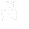
So, I am trying to use a 12V PNP Digital pressure switch to provide some automation when I activate the circuit. I want it to tell the pump to kick on basically. The output channel is only 80ma though. Here is where I am stuck but have an answer I think. Like I said I'm very new to this.
Plan to supply the Pressure Switch with its own DC source from the 8CH power supply.
Now with only 80ma for the output channel on the pressure switch, can I run it into a transistor (please specify PNP or NPN) base with the collector tying to my CH 1 COM (+) Lead ^^^ from above and the emitter tying to the "(+)" on the pump and the "(-)" on the pump tying to the ground bar?
Do I need a resistor before I tie the pressure switch output to the base terminal?
What OHM?
I apologize, I am very willing to learn. I plan to get books. My main problem now is understanding the symbols and what their function is. Like I said I am at diode level so layman help is much appreciated. Please throw some simple equations and laws up that may help me out! I am pretty good with math I just need the formula! Thanks to all that can help
Matt


