Currently I'm designing a preamp for a project. And requirements would be having common emitter as an active mixer, the first stage of the Pre amp would be a common base and finally the second stage of the preamp would be a common emitter
and I appreciate some advice on this matter.
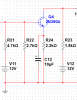
Here is an image of what I already have

Second transistor is a First Stage of the preamp (Common Base)
200 = AVNL (No load voltage gain)
98 = AVL (With load voltage gain)
23 ohms = Zi (Input Impedance )
3.3k ohms = Zo (output impedance)

Third transistor is a Second Stage of the preamp (Common Emitter)
10 = AVNL (No load voltage gain)
3.2k ohms = Zi (Input Impedance )
3.3k ohms = Zo (output impedance)

by the way
I have no problems at the first transistor (active mixer)
but is it acceptable that the No load voltage gain of the second transistor would drop to almost half when connected to a load?
and I appreciate some advice on this matter.
Here is an image of what I already have
Second transistor is a First Stage of the preamp (Common Base)
200 = AVNL (No load voltage gain)
98 = AVL (With load voltage gain)
23 ohms = Zi (Input Impedance )
3.3k ohms = Zo (output impedance)
Third transistor is a Second Stage of the preamp (Common Emitter)
10 = AVNL (No load voltage gain)
3.2k ohms = Zi (Input Impedance )
3.3k ohms = Zo (output impedance)
by the way
I have no problems at the first transistor (active mixer)
but is it acceptable that the No load voltage gain of the second transistor would drop to almost half when connected to a load?