Hi all,
I'm trying to solve the exercise found on page 107 of the 2nd edition of the art of electronics. The question asks:
Design a transistor switch circuit that allows you to swith two loads to ground via saturated NPN transistors. Closing switch A should cause both loads to be powered, whereas clsoing switch B should power only one load. Hint: Use diodes.
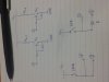
Here's a picture of the sketch of my schematic which sort of works:
![WP_20150719_21_13_28_Pro[1].jpg](https://makerv2.webteractive.co/forums/data/attachments/19/19399-58fc2556f7058ceae529ddd2b24466be.jpg "WP_20150719_21_13_28_Pro[1].jpg")
I've used LEDs for the load. The circuit works in the following way. When button A is pushed sufficient of the voltage gets to the transistor bases that both LEDs light up despite one transistor having a diode in series with its base. When button B is pushed however the circuit voltage is reduced by the variable resistor such that only the LED sinking into the transistor with the diode on its base lights. So the circuit sort of works.
However, it has several issues.
1. The non diode base LED had to be put on the emmitter side of its transistor otherwise it was constantly lit (even when the breadboard power supply was connected to the mains but switched off!?)
2. The diode base LED lights much more dimly when button B is pushed than when button A is pushed, so the loads are not equally powered by the different button for obvious reasons.
3. I would expect the non diode base LED to be the one to light when button B is pushed because that is the easier path when there is limited voltage supply.
If anyone is able to point me back to parts of chapter 2 in the book to go back and re-read to understand the question better then that would be helpful, alternatively if anyone can explain why 1 and 3 above were happening that would be good too.
I expect the first question people ask will be what are the component values. I used 330 resistors, standard LEDs and IN1448 diodes. Not sure what exactly the transistors are. The voltage is 5V and I've no idea of the value of the potentiometer as I salvaged it from some old electrical item.
Cheers,
I'm trying to solve the exercise found on page 107 of the 2nd edition of the art of electronics. The question asks:
Design a transistor switch circuit that allows you to swith two loads to ground via saturated NPN transistors. Closing switch A should cause both loads to be powered, whereas clsoing switch B should power only one load. Hint: Use diodes.
Here's a picture of the sketch of my schematic which sort of works:
I've used LEDs for the load. The circuit works in the following way. When button A is pushed sufficient of the voltage gets to the transistor bases that both LEDs light up despite one transistor having a diode in series with its base. When button B is pushed however the circuit voltage is reduced by the variable resistor such that only the LED sinking into the transistor with the diode on its base lights. So the circuit sort of works.
However, it has several issues.
1. The non diode base LED had to be put on the emmitter side of its transistor otherwise it was constantly lit (even when the breadboard power supply was connected to the mains but switched off!?)
2. The diode base LED lights much more dimly when button B is pushed than when button A is pushed, so the loads are not equally powered by the different button for obvious reasons.
3. I would expect the non diode base LED to be the one to light when button B is pushed because that is the easier path when there is limited voltage supply.
If anyone is able to point me back to parts of chapter 2 in the book to go back and re-read to understand the question better then that would be helpful, alternatively if anyone can explain why 1 and 3 above were happening that would be good too.
I expect the first question people ask will be what are the component values. I used 330 resistors, standard LEDs and IN1448 diodes. Not sure what exactly the transistors are. The voltage is 5V and I've no idea of the value of the potentiometer as I salvaged it from some old electrical item.
Cheers,
")