Hi. I am a beginner with electronics and am trying to fix a Star Trac Stepper 4100 with consistent resistance.
It doesn't matter which level I use from 1-30 the resistance is always consistent.
The only time there is no resistance is when I first step into the machine until the display turns on, and from that moment all remains the same.
I have partially dismantled the trainer and it seems mechanically intact.
Problems I have found so far:
-Display was not working
-Dead battery. 6v battery - charging by an alternator doesnt' seem to be working.
-Commutator was dirty due to carbon from the brushes.
-No resistance
Attempts of fixes so far:
-Bought a new battery and also was able to recharge the previous one saving it
-Removed the brushes and cleaned it as well as the commutator.
Results:
-Display started working
-Resistance started working, but it is constant no matter the level I use 1-30
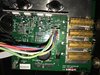
The machine is out of support and there isn't any specification of the main board to understand what to do next. I tested the capacitors. resistors, some on circuit, some by testing on circuit, others by removing them.
Here are some rough measurements from the PCB parts:
(ITEM) (SPECS) (MEASURED)
RESISTOR
R1 VI OR WH WH YE = 499k (486.7k)
R2 GO YE BK BR = 100k (97.5k)
R3 GO YE BK BR = 100K (98.6k)
R4 BR BK OR GO = 10K (9.84K)
R5 GO YE BL BR = 100K (98.6K)
R6 GO OR BL BR = 10K (9.81K)
R7 RE BK RE GO = 2K (1.973K)
R8 OR BL GRE BR BR = 3.65K (3.64K)
R9 YE WH WH BK BR = 499 (497.5)
R10 RD BK BK BK BR = 200 (199.5)
R11 BR BR RE GY BR = 1.82K (1.765K)
R12 GO YE BK BR = 100k (98.6k)(93.1k)
R13 GO OR BK BR = 10k (9.82k)
R14 BR BK OR GO = 10K (9.86k)(8.32k)
R15 GO OR BK BR = 10K (9.84K)
R16 BR BK OR GO = 10K (9.83K)
R17 YE VI BR GO = 470 (464.3)
R18 GO YE BK BR = 100K (96.9K)
R19 YE VI GRE RE BR = 47.5K (47.54K)
R20 BR BK BK BR BR = 1K (0.904) (0.995 - after removing)
R21 BR BK BK BR BR = 1K (0.993)
R22 GO GO GR BLU = 6.8 (6.6)
R23 GO OR BK BR = 10k (4.03K) (9.85k - after removing)
R24 GO YE BK BR = 100K (93.2K) (98.4k - after removing)
R25 GO OR BK BR = 10K (9.8k)
R26 BR BR BK BK BR = 1K (0.995K)
R27 BR BK BK BR BR = 1K (1k)
R28 RE BK BK BK BR = 200 (200)
R29 - dale rh50 50w 1ohm m10505 - 0.9
R30 - dale rh50 50w 1ohm m10505 - 0.9
R31 - dale rh50 50w 1ohm m10505 - 0.5 (1.00 after removing)
R32 - dale rh50 50w 1ohm m10505 - 0.5 (1.00 after removing)
DIODES
D1 (304 / 304) (~500 / 0 - normal after removing)
D2 (495 / 558) (~500 / 0 - normal after removing)
D3 (452 / 1)
D4 (455 / 1)
D5 (450 / 1)
D6 (470 / 1)
D7 (133 / 1 (spike then 1))
D8 (134 / 1)
D9 (488 / 1)
D10 (132 / 1)
D11 (653 / 1 (spike then 1))
CAPACITORS
C1 50v 100nf (327.5nf)(no reading) (model 104 ceramic orange)
C2 50v 100nf 0.1uf (102.4nf) (model 104 ceramic orange)
C3 50v 10nf 0.01uf (10.2nf) (model L48 103 ceramic brown)
C4 25v 10000uf (9.955mf)
C5 25v 22uf (22uf)
C6 25v 22uf (remove and test) (23uf after removing)
C7 25v 22uf (23.66uf)
C8 25v 100uf (109uf)
C9 25v 22uf (23uf)
C10 25v 100uf (103.3uf)
C11 50v 100nf (103.1uf) (model 104 ceramic orange)
Q - Transistors
Q1 - MPS2 - 222A - 437
Q2 - MPS2 - 222A - 437
Q3 - MPS - A13 - M910
Q4 - MPS2 - 222A - 437
Q5 - TIP127 (CQ419)
Q6 - TIP32
Q7 - PN2 907A M918
Q8 - TIP122
NPN Transistor:
T1 2N3771 - BM0523
T2 2N3771 - BM0523
It will be nice to get some hints what to do next so I can save this machine from going to waste.
Thank you all for reading.
It doesn't matter which level I use from 1-30 the resistance is always consistent.
The only time there is no resistance is when I first step into the machine until the display turns on, and from that moment all remains the same.
I have partially dismantled the trainer and it seems mechanically intact.
Problems I have found so far:
-Display was not working
-Dead battery. 6v battery - charging by an alternator doesnt' seem to be working.
-Commutator was dirty due to carbon from the brushes.
-No resistance
Attempts of fixes so far:
-Bought a new battery and also was able to recharge the previous one saving it
-Removed the brushes and cleaned it as well as the commutator.
Results:
-Display started working
-Resistance started working, but it is constant no matter the level I use 1-30
The machine is out of support and there isn't any specification of the main board to understand what to do next. I tested the capacitors. resistors, some on circuit, some by testing on circuit, others by removing them.
Here are some rough measurements from the PCB parts:
(ITEM) (SPECS) (MEASURED)
RESISTOR
R1 VI OR WH WH YE = 499k (486.7k)
R2 GO YE BK BR = 100k (97.5k)
R3 GO YE BK BR = 100K (98.6k)
R4 BR BK OR GO = 10K (9.84K)
R5 GO YE BL BR = 100K (98.6K)
R6 GO OR BL BR = 10K (9.81K)
R7 RE BK RE GO = 2K (1.973K)
R8 OR BL GRE BR BR = 3.65K (3.64K)
R9 YE WH WH BK BR = 499 (497.5)
R10 RD BK BK BK BR = 200 (199.5)
R11 BR BR RE GY BR = 1.82K (1.765K)
R12 GO YE BK BR = 100k (98.6k)(93.1k)
R13 GO OR BK BR = 10k (9.82k)
R14 BR BK OR GO = 10K (9.86k)(8.32k)
R15 GO OR BK BR = 10K (9.84K)
R16 BR BK OR GO = 10K (9.83K)
R17 YE VI BR GO = 470 (464.3)
R18 GO YE BK BR = 100K (96.9K)
R19 YE VI GRE RE BR = 47.5K (47.54K)
R20 BR BK BK BR BR = 1K (0.904) (0.995 - after removing)
R21 BR BK BK BR BR = 1K (0.993)
R22 GO GO GR BLU = 6.8 (6.6)
R23 GO OR BK BR = 10k (4.03K) (9.85k - after removing)
R24 GO YE BK BR = 100K (93.2K) (98.4k - after removing)
R25 GO OR BK BR = 10K (9.8k)
R26 BR BR BK BK BR = 1K (0.995K)
R27 BR BK BK BR BR = 1K (1k)
R28 RE BK BK BK BR = 200 (200)
R29 - dale rh50 50w 1ohm m10505 - 0.9
R30 - dale rh50 50w 1ohm m10505 - 0.9
R31 - dale rh50 50w 1ohm m10505 - 0.5 (1.00 after removing)
R32 - dale rh50 50w 1ohm m10505 - 0.5 (1.00 after removing)
DIODES
D1 (304 / 304) (~500 / 0 - normal after removing)
D2 (495 / 558) (~500 / 0 - normal after removing)
D3 (452 / 1)
D4 (455 / 1)
D5 (450 / 1)
D6 (470 / 1)
D7 (133 / 1 (spike then 1))
D8 (134 / 1)
D9 (488 / 1)
D10 (132 / 1)
D11 (653 / 1 (spike then 1))
CAPACITORS
C1 50v 100nf (327.5nf)(no reading) (model 104 ceramic orange)
C2 50v 100nf 0.1uf (102.4nf) (model 104 ceramic orange)
C3 50v 10nf 0.01uf (10.2nf) (model L48 103 ceramic brown)
C4 25v 10000uf (9.955mf)
C5 25v 22uf (22uf)
C6 25v 22uf (remove and test) (23uf after removing)
C7 25v 22uf (23.66uf)
C8 25v 100uf (109uf)
C9 25v 22uf (23uf)
C10 25v 100uf (103.3uf)
C11 50v 100nf (103.1uf) (model 104 ceramic orange)
Q - Transistors
Q1 - MPS2 - 222A - 437
Q2 - MPS2 - 222A - 437
Q3 - MPS - A13 - M910
Q4 - MPS2 - 222A - 437
Q5 - TIP127 (CQ419)
Q6 - TIP32
Q7 - PN2 907A M918
Q8 - TIP122
NPN Transistor:
T1 2N3771 - BM0523
T2 2N3771 - BM0523
It will be nice to get some hints what to do next so I can save this machine from going to waste.
Thank you all for reading.