Okay. Just got off the phone with Grizzly (the manufacturer) about this lathe. Here's what I know so far.
The lathe was given to my shop (a band instrument repair shop). I do not know anything about the history other than there was sticker on the top of the lathe suggesting that the only thing wrong with it was that it needed a new switch. (Not the case.)
My suspicions are that the original owner probably had a near death experience using the tool and managed to damage the internals somehow, but that is purely speculation.
SO...
My problem at this point is that I need replace a potentiometer that I have no information for. Quite literally, what would be the housing of the back part of the potentiometer is gone, so I have no idea what the specs are for the part. I spent an hour on the phone with the manufacturer while their technical people looked for information on the unit, but they were unable to come up with enough information to offer a solution they felt good about. I was told that the original manufacturer of the pot went bankrupt.
At any rate, the wires and electronics had been dismantled and left in shambles when it came to me. Here are some photos of my reconstruction of what needs to be where. Grizzly did send me a very poor quality wiring diagram, but again it has no actual specs on it.
Close up of the motor:

Bird's eye view of everything. To the left is what's left of the pot. The pot was mounted in the faceplate next to on/off switch, and the fuse holder you see was mounted in the faceplate also. This is just laid out so I could figure out where it all was supposed to go.
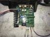
Close up of circuit board:

Close up of damaged fuse holder which had the wrong fuse installed - Fuse required is a 10A 250V.

Wires from circuit board to pot:

Remains of pot:


Under side:

And here's a spec sheet and wiring diagram (a poor one) from the manufacturer.


That's all I have on this. Can this be determined? I am not an experienced electronics person, but I'm not totally ignorant either. If someone has sites or suggestions on where to get parts, etc. I'm wide open to any advice. Thanks to everyone who takes a look at this.
Jeremy
The lathe was given to my shop (a band instrument repair shop). I do not know anything about the history other than there was sticker on the top of the lathe suggesting that the only thing wrong with it was that it needed a new switch. (Not the case.)
My suspicions are that the original owner probably had a near death experience using the tool and managed to damage the internals somehow, but that is purely speculation.
SO...
My problem at this point is that I need replace a potentiometer that I have no information for. Quite literally, what would be the housing of the back part of the potentiometer is gone, so I have no idea what the specs are for the part. I spent an hour on the phone with the manufacturer while their technical people looked for information on the unit, but they were unable to come up with enough information to offer a solution they felt good about. I was told that the original manufacturer of the pot went bankrupt.
At any rate, the wires and electronics had been dismantled and left in shambles when it came to me. Here are some photos of my reconstruction of what needs to be where. Grizzly did send me a very poor quality wiring diagram, but again it has no actual specs on it.
Close up of the motor:
Bird's eye view of everything. To the left is what's left of the pot. The pot was mounted in the faceplate next to on/off switch, and the fuse holder you see was mounted in the faceplate also. This is just laid out so I could figure out where it all was supposed to go.
Close up of circuit board:
Close up of damaged fuse holder which had the wrong fuse installed - Fuse required is a 10A 250V.
Wires from circuit board to pot:
Remains of pot:
Under side:
And here's a spec sheet and wiring diagram (a poor one) from the manufacturer.
That's all I have on this. Can this be determined? I am not an experienced electronics person, but I'm not totally ignorant either. If someone has sites or suggestions on where to get parts, etc. I'm wide open to any advice. Thanks to everyone who takes a look at this.
Jeremy