Maker Pro
Maker Pro

Trying to create a sunrise/sunset power up/down LED strip

This is something I want to make for an aquarium, but I'm a novice with electronics. Here are my constraints:
  • When power is applied I want LEDs to slowly power up (15-30 minutes) and when power cut to slowly power down (15-30 minutes). Very gradual.
  • Don't want to use a battery, want to use capacitors
  • Want to keep capacitance at "safe to handle" levels. If it becomes a serious shock risk, then I can compromise on power up/down time. 10 minutes at least I'd say but prefer longer.
LED strip I'm using 5 meter strip:
* 4.92 A
* 59 W
* 12 V

I found a YouTube video with instructions online, unfortunately the creator's suggested max amperage is too low.

_screenshot_
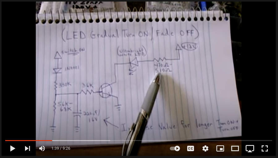
A2gtPpJ.png


Does anyone know how I can update this circuit for my needs? Any help is much appreciated!
 
Welcome to EP!
An analogue circuit using discrete components similar to those in the video is totally unsuitable for ramp times more than just a few seconds. A microcontroller or some other digital timer would be the preferred tool for the job.
want to use capacitors
What for?
If it becomes a serious shock risk
Why would it? Your LED strip requires just 12V, which is not a shock risk (unless applied through your skin).
 
Last edited:
Basically, that's a lot of lighting for a long time. Maybe need to revise your aims.

59 watts of lighting, for 30 minutes, if full one, is 59*30*60 = 100KJoules, so given that it's dimming, let's say 50KJ needed.
A conversion system 100% efficient from storage to lighting, and l;et's say as suggested stored at 12volts
Energy in capacitor E = 1/2 C V^2, so capacitor needed about
C = 2*E/(V^2) = 2* 50E3 /(144) = 737 Farads.
Did I goof that up?
.
So, options include storing at higher voltage and adding something to do the conversion? That v^2 helps there.
Maybe consider a power supply, or battery?
.
As pointed out above, very long time constants with analog are rather tricky, usually digital is easier.
There are lots of examples out there for led strips controlled by arduino, pis or similar. Digital input LEDs are convenient, easy. Maybe worth a look.
 
Thanks all for input. OK sounds like I need to investigate the microcontroller/timer route. These components are all going into what will be a permanently enclosed and waterproofed aquarium hood, so whatever approach I use I don't want there be be any need for maintenance. I was worried batteries would require replacement with age.
 
59W dissipated in a sealed enclosure could make things quite toasty, unless your enclosure design provides some heat-sinking, e.g by having a large metallic surface area.
59W is a lot of light. How big is the aquarium? If only a modest size, then the fish will need sunglasses :)
 

Harald Kapp

Moderator
Moderator
A few thoughts:
  • Dimming (on and off) can be easily done by a microcontroller, e.g. Arduino. Lots of examples out there, code is rather simple. Such a circuit could also be equipped with other sensors for e.g. temperature and environmental light to be used in the decision how much light is required. Or as an additional alarm if something is wrong with the aquarium. Just sone random thoughts of mine, absolutely not required.
  • Analog dimming could be done with e.g. a 555 timer, at less accuracy than using a microcontroller. But that is probably not an issue at all with aquarium lighting. But in order to be reasonably energy efficient, one would use PWM for dimming, not the analog method used in the video. Analog dimming is utterly inefficient and a no-go at the power levels being employed here. An analog circuit with timer and PWM is probably much more complex and definitely less flexible than a microcontroller solution.
  • Using capacitors to supply power for the turn-off phase is out of the question as @Nanren888 has shown. Rechargeable batteries are possible.
    Is there a reason you need to completely turn-off the lights by removing them from mains? In this situation I would go for a permanent power supply (12 V) and control on/off by an input to the microcontroller that does the dimming. Thus you can draw power from mains during the turn-off phase without the need for batteries.
  • If you insist on batteries, a similar calculation as @Nanren888 has made for batteries is as follows:
    59 W max. averaged through dimming over the turn-off phase is ~ 30 W mean power dissipation. Energy required is 30 W × 0.5 h = 15 Wh. Accounting for conversion losses (assuming you will not use a 12 V lead battery), the rated capacity of the battery should be 20 Wh or more. Such a battery is around 20 $ (give or take) plus you will need circuitry to properly charge the battery and protect the battery from over discharging.
  • @Alec_t : LED lighting with 59 W sound a lot. It is equivalent to ~4200 lumen acc. to the specs of the LEDs. According to this site an aquarium needs between 10...40 lumen per liter, depending on the requirements of the plants in the aquarium. 4200 lumen are then good for 420...105 liters. This doesn't sound unreasonable to me.
    Of course the dissipated power (waste heat) needs to be removed by adequate cooling.
 
That is a lot of heat.
In days gone by we used to use a 10W pilot bulb inside an old refrigerator as a heat source to keep welding rods dry.
Even at that, the rods were extremely hot.

So unless your plan is to add chips to those fish............o_Oo_O
 
59W dissipated in a sealed enclosure could make things quite toasty, unless your enclosure design provides some heat-sinking, e.g by having a large metallic surface area.
59W is a lot of light. How big is the aquarium? If only a modest size, then the fish will need sunglasses :)
That is a lot of heat.
In days gone by we used to use a 10W pilot bulb inside an old refrigerator as a heat source to keep welding rods dry.
Even at that, the rods were extremely hot.

So unless your plan is to add chips to those fish............o_Oo_O
The LEDs will actually be outside the hood on the bottom. I have a 1st gen of this hood without fade-in/fade-out and the heat level isn't that bad, but I'll add a vent JIK.
 
A few thoughts:
  • Using capacitors to supply power for the turn-off phase is out of the question as @Nanren888 has shown. Rechargeable batteries are possible.
    Is there a reason you need to completely turn-off the lights by removing them from mains? In this situation I would go for a permanent power supply (12 V) and control on/off by an input to the microcontroller that does the dimming. Thus you can draw power from mains during the turn-off phase without the need for batteries.

My original plan was to keep using the same mechanical timer outlet I have. Power on/off was going to start the fade on/off cycle based on charging/discharging the capacitor.
 

Harald Kapp

Moderator
Moderator
The Arduino could do the timing, too. With a real time clock module added you could even program seasonal on/off times, or throw in a light sensor so the aquarium lights are on only if no natural light is available.
I would use a microcontroller anyway for the dimming.

If you want to stick to the battery solution, you'll need:
- a power supply that can deliver the power for the LEDs plus some more for charging the battery. A 12 V 70 WE power supply should be sufficient.
- a suitable battery (12 V, >= 20 Wh) plus a charger circuit to charge the battery from the 12 V power supply. Ideally the battery controller provides charging and undervoltage protection so power from the battery will be turned off if the battery is insufficiently charged. This will increase the lifetime of the battery considerable,
- a controller to control dimming during turn-on and turn-off. The controller also needs an input to sense the 12 V from the power supply to "know" when power is turned on and off. I doubt you can find such an item off the shelf. But it is easy to construct from e.g. an Arduino.
- If you use an Arduino, you will need a driver module to supply power to the LEDs (the Arduino can generate the PWM control signal, but cannot supply the power).
- Optionally you may use an additional volatge regulator to step down the 12 V from the battery or power supply to a more manageable 9 V for the Arduino. While an Arduino can be powered by 12 V, the internal voltage regulator may become a bit warm. This is reduced by powering the Arduino from only 9 V.
 
If you place a strip of white LEDs inside an opaque container you can use a simple clock and decimal stage counter to switch on the LEDs in sequence (from zero on to 'all' on in whatever-second steps you require). The opaqueness might be able to hide the individual point-lights. A bit 'mechanical' but workable.

I'm also imagining a tube with a strip of LEDs wrapped around it (spiral column) using a WS2812 addressable LED strip with an Arduino - the libraries to drive them are readily available and you can even have incremental brilliance on each individual LED (not to mention full RGB colour control).
 
Top