Hi guys,
Firstly, I am by no means experienced with electronics, so if I say something stupid, please forgive me.
I am working on an interlock system for a project I'm assigned to as part of an industrial placement, and I am not sure how to overcome a couple of issues.
The way the interlock works is as follows;
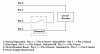
In normal operation of the system, two separate sets of 24V lines are shorted to each other, i.e. pins 1&4 and pins 2&3 on the serial interface are connected.
When one of these lines is opened the system shuts down, and in order to get it powered up again the un-opened line needs to be opened and then both lines need to be closed.
One of these lines is operated on a switch, and as such poses no problem, but unfortunately that is not an option for the second line.
So, my goal is to somehow automatically trigger the opening and closing of the second line when the first line has been broken.
I was thinking along the lines of a monostable 555 timer circuit with its output connected to a relay, which would open the second line for a period of time defined by the 555 circuit, then close it again, but my problem is how to go about triggering the 555 timer circuit on the breaking of the first line?
Any help with accomplishing the above, or any suggestions on alternative methods would be greatly appreciated.
Thanks
Firstly, I am by no means experienced with electronics, so if I say something stupid, please forgive me.
I am working on an interlock system for a project I'm assigned to as part of an industrial placement, and I am not sure how to overcome a couple of issues.
The way the interlock works is as follows;
In normal operation of the system, two separate sets of 24V lines are shorted to each other, i.e. pins 1&4 and pins 2&3 on the serial interface are connected.
When one of these lines is opened the system shuts down, and in order to get it powered up again the un-opened line needs to be opened and then both lines need to be closed.
One of these lines is operated on a switch, and as such poses no problem, but unfortunately that is not an option for the second line.
So, my goal is to somehow automatically trigger the opening and closing of the second line when the first line has been broken.
I was thinking along the lines of a monostable 555 timer circuit with its output connected to a relay, which would open the second line for a period of time defined by the 555 circuit, then close it again, but my problem is how to go about triggering the 555 timer circuit on the breaking of the first line?
Any help with accomplishing the above, or any suggestions on alternative methods would be greatly appreciated.
Thanks
")