Hi!
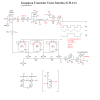
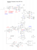
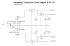
I am about to CAD the layout for my transistor tester according to below.
It is preliminary set to give curves for Id/Ic less than +/-80mA using TLE2064 as OP.
My design is finished but there has recently emerged a need for higher currents and thus power devices (LU1014D).
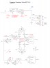
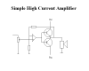
So I am thinking of adding the first schematic in my thread "What is the most simple PA?" (also attached for convenience) to the output of TLE2064 while putting an ordinary 6A fuse at output.
I do however have another idea. That is to use a PWM-supply normally used for motor drive which is ready awailable at work (24V/5A).
It is possible to control both current and voltage with this device. And it all comes in a nice 4"X4"X4" package. Supply transformer included, of course.
But I do not know. It feels like the simple PA will be my choice. Mainly because the motor drive is switching and there might be disturbing ripple while measuring small Ic/Id.
On the other hand, I could always add an extra LC-filter...
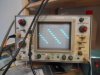
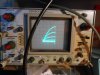
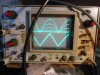
Anyway, I am attaching my schematics and some photos. It has not been fully tested yet but I am quite certain it will work. But if you see anything strange, don't be shy")
Take care!
Best regards, Roger
PS
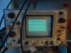
The graph is for BF245A. X is 1V/DIV, I think. But it looks like 0,5V/DIV for some strange reason that I do not remember. Yet it seems true that the transistor has not become "fully working" at 3,5Vds. It looks like Y is set at 0,1V/DIV. Using 10 Ohm this would mean 10mA/DIV. But we all know that can't be true for BF245A so I suspect I used 100 Ohm in this case, giving 1mA/DIV. I am quite sure that Vgs goes from 0V to -5V in seven equal steps.
I am about to CAD the layout for my transistor tester according to below.
It is preliminary set to give curves for Id/Ic less than +/-80mA using TLE2064 as OP.
My design is finished but there has recently emerged a need for higher currents and thus power devices (LU1014D).
So I am thinking of adding the first schematic in my thread "What is the most simple PA?" (also attached for convenience) to the output of TLE2064 while putting an ordinary 6A fuse at output.
I do however have another idea. That is to use a PWM-supply normally used for motor drive which is ready awailable at work (24V/5A).
It is possible to control both current and voltage with this device. And it all comes in a nice 4"X4"X4" package. Supply transformer included, of course.
But I do not know. It feels like the simple PA will be my choice. Mainly because the motor drive is switching and there might be disturbing ripple while measuring small Ic/Id.
On the other hand, I could always add an extra LC-filter...
Anyway, I am attaching my schematics and some photos. It has not been fully tested yet but I am quite certain it will work. But if you see anything strange, don't be shy
Take care!
Best regards, Roger
PS
The graph is for BF245A. X is 1V/DIV, I think. But it looks like 0,5V/DIV for some strange reason that I do not remember. Yet it seems true that the transistor has not become "fully working" at 3,5Vds. It looks like Y is set at 0,1V/DIV. Using 10 Ohm this would mean 10mA/DIV. But we all know that can't be true for BF245A so I suspect I used 100 Ohm in this case, giving 1mA/DIV. I am quite sure that Vgs goes from 0V to -5V in seven equal steps.