Maker Pro
Maker Pro

Traffic Light project

I've had a vintage traffic light that my dad gave me for many years. I want to do something with it. I'm not an electronics genius but I did take electronics in high school.

I want to have it take an audio line in and convert the signal to 3 possibilities on the light. Like red for bass, yellow for mid-range and green for treble. The light has 3 wires. black, green, yellow and red naturally.

Any ideas and where do I start?

Start by thinking out exactly how you want it to function:
-Lights on/off only depending on level of bass, mid, and tebble ?
-Lights fade depending on level?

Depending on your desire, you may need to gut the light and build your own light source.
 
Start by thinking out exactly how you want it to function:
-Lights on/off only depending on level of bass, mid, and tebble ?
-Lights fade depending on level?

Depending on your desire, you may need to gut the light and build your own light source.
I dont know if I want to gut the light. I was thinking more of building a box with the components in there and hook it up to the 4 wires.

on/off to a signal that can be adjusted by a variable capacitor would work?
 
Yes, that would work.
I don't have example circuits on hand, but you're going to need some filters.
Your magic box will essentially be one circuit built 3 times with a different filter on it.
Your circuit will consist of an input filter to dictate bass, mid, or treble frequency response.
The signal is then fed into a comparator to trigger an output when the level of the filtered signal exceeds the value you have set with your potentiometer. (To adjust sensitivity)
The only concern I have is the frequency that the bulbs may end up switching on and off.

*Your filters will be simple rc filters. If you want to learn how to build them, google around for 'cross over filter' as they will give you some good intel on how they work, and how to tune them.
Thanks! Sounds like a good start. I drew up this quick schematic which is about the limit of my electronic know-how. :) Can you help me fill in the blanks?
traffic_light.jpg
 
haha, well... You gotta start somewhere. We have another guy on here that uses paint to draw things ;)

You will most likely want to use more than one potentiometer.
A Master that is externally available to adjust as a 'master' volume, and smaller potentiometers inside the magic box that will allow you to adjust sensitivity per channel, and alight adjustment to the frequency you want passed through.

I'd like to help you learn, so before I give you the diagram, im going to tell you to do a little google search for "RC Highpass", "RC Bandpass", and "RC Lowpass" these are very very simple circuits requiring only a small number of capacitors and resistors (4 of each to build all 3)
Your input will go to your Master Potentiometer to adjust overall sensitivity, then will branch off to each of the 3 types of filters. Each filter will go to its own comparator which we can look at shortly.

*How do you plan to connect this?
Using the 'Line-out' of an audio device is different from using a headphone jack. This is due to a different impedance from the source. It would help to know to help ensure we don't inadvertently alter the sounds too much.
Do you plan to put in a built in speaker?
You should probably add a second RCA or 1/8" connector as a passthrough so that you don't have to worry about messing with Y-cables. ;)


Edit: More homework.
Figure what frequency you want to consider 'Bass' and 'Treble' and what range you want as 'mid'
There are a set of loose standards. You can play with Audacity or other audio editing software to listen to a song after you send it through a 'low-pass' to see what it sounds like. By playing with the numbers like this. You can determine what would work well for your particular tastes... (ie. red light on drums, or only for the really low notes from Dubstep)
Remember that this circuit works based on how large the signal is... it will not be able to pick out certain instruments if there is another sound in the same frequency group that is louder.
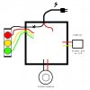
 
Last edited:
Well I used Photoshop so I got one up on that guy! ;)

Okay, I get the jist of where this is going. Going to do my homework and I'll get back to you. Thanks!!!
 

KrisBlueNZ

Sadly passed away in 2015
The thing you're making is called a "color organ". Start with a Google image search for color organ schematic, and find the relevant pages from there.
 
Top