Maker Pro
Maker Pro

Toggle Switch - Momentary Pulse Circuit (problem!)

Hi I am new to all of this but I do have a breadboard and some stuff lying around so I thought I would give this a go!

I have want to use a toggle switch to "pulse" a keyboard key for use in a flight simulator however I just want to get it working with a LED for now!

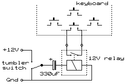
I used the following diagrams to try and hook this up so when I flick the toggle switch the LED will blink momentarily (this will be a key press and release eventually) but it just does nothing! Have I got the wrong parts, have I messed up the wiring? Hopefully someone will know! The only difference I can see is that I am using a 5v power and relay.

The diagrams I followed where Keyboard is an LED:
Image12.gif

relay.jpg


My current setup:

5V 1.0AMP USB Power - iPhone Plug + USB Cable

5V SPDT Relay (RAYEX ELEC LU-5)
Purchased from http://www.maplin.co.uk/p/5v-dc-2a-spdt-sub-miniature-relay-n16aw

220uF 50V 105(degrees) Capacitor

On-Off-On Toggle Switches
https://www.amazon.co.uk/dp/B01DEM2...qid=1468357811&sr=sr-1&keywords=toggle+switch

mine.jpg


Are my parts all compatible? Do i need 12v power? I am so confused!!

If anyone could lend a hand that would be really appreciated!! I don't want to have to pay £40 for some board that pulses toggle switches for me, I'm more of a DIY kind of guy!
 
Last edited:
Perhaps the energy given by the 330μF capacitor is sufficient to light the led but insufficient to switch the relay.
You could use a 555 monostable to give a fairly hefty pulse.
 
Perhaps the energy given by the 330μF capacitor is sufficient to light the led but insufficient to switch the relay.
You could use a 555 monostable to give a fairly hefty pulse.
Thanks for the reply, I'm currently using a 220, from what I gathered this value would just change the length of time the LED would be on before flicking off? Would a higher uf capacitor be better? I hear you with the 555 but I want to keep this as simple as possible as there will be quite a few more switches once I get one working! Just to be clear the circuit does nothing at all to the LED.
 
I believe You have Power to the Relay Coil, But No power to the LED.
Right, is this because in the schematic I followed, they have a keyboard switch, which ovioisly doesn't need power i am just closing it, where as my LED just does nothing because I am giving it no power? So if I split the LED out and give it power and use the relay to complete the circuit momentarily o should see it working?
 
I'd say get the relay clicking first then add your LED circuit afterwards.
Obviously you are getting confused on the operating requirements so one bit at a time will help you.
Just a note.....some of these small 5v relays are polarised,
I've been caught with that before.o_O
 
I'd say get the relay clicking first then add your LED circuit afterwards.
Obviously you are getting confused on the operating requirements so one bit at a time will help you.
Just a note.....some of these small 5v relays are polarised,
I've been caught with that before.o_O
Thanks for the help! How can I check if the relay is clicking? Is there a simpler way than with the LED? Also if it is polarised, which wires would I have to switch? Thanks again really appreciate it!
 
[QUOTE="KiwiElectronics, post: 1699602, member: 44904" How can I check if the relay is clicking? [/QUOTE]

Just turn off your ghetto blaster.:)

The 'breadboard' does not seem to have a power supply for the led (see #4). You could take some from the 5V supply but will need a series resistor.
 
Haha damn no wonder I couldn't hear the click!!

Just a quick one if I am using multiple switches on one power would something like this work to have 8 independent switches controlling 8 different keyboard keys?

Am I right in thinking each relay is 40ma and I have 1a so 8 should run fine?

I can see on this bank of 8 relays the 3 holes for the keyboard wires but where would my toggle switch / capacitor attach? The more I look at these the more I question if they are totally the wrong thing!!

https://www.ebay.co.uk/itm/191765757093

Thanks!
 
Last edited:
That bank of relays seems to have transistors to feed the relay coil so should be much more sensitive than the ones you have but you will have to observe polarity.
 
That bank of relays seems to have transistors to feed the relay coil so should be much more sensitive than the ones you have but you will have to observe polarity.

Ok thanks for the info, will I have to change my setup at all in terms of capacitors etc or will what I am using still work even though they are sensitive?

Oh by the way I replaced the LED with the keyboard switch and it worked like a dream!! So thanks guys I would have been scratching my head with that one for a long long time!
 
I do not know what the drive circuit of the relays is. I would think that you will need a smaller capacitor and maybe a series resistor to lengthen the on time.
 
Top