Maker Pro
Maker Pro

Timelapse Electronics

Hi my son is an aerospace engineer and has designed and made a time lapse bed for his camera.

Wer are having problems with the electronic side though we did have it up and running but circuit board soldering etc is not our strong points and we cannot seem to get it up and running again and have blown several boards since.

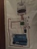
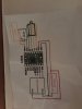
The board is an Arduino with a Reprap Stepstick board motor driver to control a four wire stepper motor I have wiring diagrams etc, is there anyone in the UK that could help us with the wiring happy to pay or post etc. Its a shame because we are so close but just cant get this bit right.

please contact me if you can help.

Thanks Neill
 
Welcome to EP.

Parts can blow not only because of bad wiring.
Mistakes in design are one very common cause,especially for new designs .
Please post the schematics,so we can review it for potential problems.
 
Welcome to EP.

Parts can blow not only because of bad wiring.
Mistakes in design are one very common cause,especially for new designs .
Please post the schematics,so we can review it for potential problems.


Hi please see attached

Thanks

Neill
 

Attachments

  • IMG_1556.JPG
    IMG_1556.JPG
    238.3 KB · Views: 68
  • IMG_1557.JPG
    IMG_1557.JPG
    216.3 KB · Views: 108

Harald Kapp

Moderator
Moderator
Your photos aer not easily read. What is the little chip in the lower right corner of the breadboard? Is it the voltage regulator (logic power supply= from your second image? If so, I'd expect 3 leads but see only 2 plus some filter capacitors (I don't see any).
Also label the little arrows in photo #1 so we can see which voltages are present.

It seems the red wire from the right side of the breadboard is going to Vin of the arduino. What voltage is present there? No more than 12 V are recommended. You should also decouple the Arduino's power supply from the motor as the motor can generate high voltage or negative voltage spikes when operating. Use a filter to reduce that noise, read this discussion. For starters, use different power supplies, one for the motor, one for the Arduino.
 
Unless the A4988 board has internal pull-up resistors the unconnected Enable, Sleep and Reset inputs are floating. This is a no-no and can lead to circuit instability, which is possibly why your boards fried. Connect these three inputs to Vdd/Arduino as appropriate (see the Typical Application schematic in the IC datasheet)
 
Hi thanks for your replies this is all beyond my capability hence asking if someone could wire correctly for us . Happy to pay etc I am no electronics expert! Give me an engine and I will fix it
 
@neill,
Before you even get to wiring you should have a solid and correct design.
Without it the best "wiring person at NASA" will not help you.
That is why the questions arise.
 
@neill,
Before you even get to wiring you should have a solid and correct design.
Without it the best "wiring person at NASA" will not help you.
That is why the questions arise.
Nothing wrong with the design I think a qualified aerospace engineer should be able to design this ok.

As I have said we have had it up and running but we do need help with the electronics side. I agree with the back feed theory from the stepper motor could have blown the board.

I was just hoping someone could help with the circuit wiring side of things.
 
Nothing wrong with the design I think a qualified aerospace engineer should be able to design this ok.

Obviously not, as you are having problems and with the questions asked, the people here are trying to help so maybe answering their queries will eventually help you.

As an added query, have you adjusted the stepper driver boards as recommended from the manufacturers.
 
Ok I was asking if someone with electronic knowledge could help with the wiring and boards I am happy to post we are no electronics experts each to there own . The design hardware is fine it's the software we need help with the questions asked are beyond my electronic knowledge hence asking if someone could help.

The circuit design came from a time lapse forum .
 

hevans1944

Hop - AC8NS
I doubt very much that software will blow boards.
Sorry, but it is easy to blow components with software by improperly controlling I/O pins. I haven't seen a single line of code posted yet, and @Alec_t has already pointed out some wiring errors in his post #6. Also sounds like @neill is asking for a personal visit (for which he seems willing to pay) to help him get it all sorted. So, if any UK EP members are willing to do that, drop him a PM and set up a meet.

Maybe he has a local makers club with members who are willing to help for free. These are springing up all over the world, but most are underfunded and not well-advertised. An amateur radio club will be easier to find, and most welcome newbies with open arms, hoping to encourage them to become licensed radio amateurs.
 

(*steve*)

¡sǝpodᴉʇuɐ ǝɥʇ ɹɐǝɥd
Moderator
Perhaps if we can have a link to the design from the time-lapse forum and an explanation of what has "blown" and why you think it has blown.

As to someone doing the writing for you, where in the Antarctic are you? I'll get the sled dogs out and come on over to help you. Can I come over tomorrow (after winter)?
 
Many thanks to heavens 1944 who explained my request very well . There is no problem with the actual design it's basically a rail bed driven by a belt round the stepper motor.

We have the programme uploaded that runs it and we know it works as we have had it running. It is purely the electronics side we are struggling with hence me asking for help and payment to resolve for us.
 
Top