Hi, I'm a tech student but not great at electronics. I'm making an audio amplifier using a TDA2009 chip, and I'm using the '10W + 10W Bridge Amplifier' circuit (schematic in attachments):
I have successfully breadboarded this circuit from this schematic and using my own circuit diagram (see attachments), and the audio is great when using the breadboard. But when I then duplicated the circuit onto a PCB for some reason it does not.
As far as I can tell the circuits are exactly the same and I (and my teachers) have double checked the components multiple times, but none of us can figure out why it doesn't work.
The speaker is quiet and crackly but you can just about hear faint music in the background, also the TDA2009 chip gets burning hot, even why I use a heat sink on it - none of this happens with the breadboarded circuit.
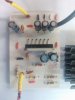
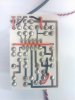
I have included an image of my PCB layout in the attachments and I am using a 30W, 8Ohm speaker (link below) with a 12V power supply.
http://www.faitalpro.com/en/products/LF_Loudspeakers/product_details/?id=401005150
I hope this all makes sense and thankyou in advance to anyone that can help me. Alex.
P.S. Please ignore some of the badly drawn capacitor symbols in my circuit diagram there obviously shouldn't be lines going through them.
I have successfully breadboarded this circuit from this schematic and using my own circuit diagram (see attachments), and the audio is great when using the breadboard. But when I then duplicated the circuit onto a PCB for some reason it does not.
As far as I can tell the circuits are exactly the same and I (and my teachers) have double checked the components multiple times, but none of us can figure out why it doesn't work.
The speaker is quiet and crackly but you can just about hear faint music in the background, also the TDA2009 chip gets burning hot, even why I use a heat sink on it - none of this happens with the breadboarded circuit.
I have included an image of my PCB layout in the attachments and I am using a 30W, 8Ohm speaker (link below) with a 12V power supply.
http://www.faitalpro.com/en/products/LF_Loudspeakers/product_details/?id=401005150
I hope this all makes sense and thankyou in advance to anyone that can help me. Alex.
P.S. Please ignore some of the badly drawn capacitor symbols in my circuit diagram there obviously shouldn't be lines going through them.
Attachments


Last edited:
")