Maker Pro
Maker Pro

Stage Lighting Followspot PCB in need of repair

Hello everyone,

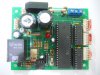
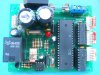
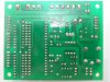
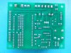
I have two of these unit that were giving problems and I actually managed to troubleshoot and repair one but I am having problems with the other pcb. The units are fairly simple. They run on 12V ~ 18V DC and are powered by a 12V toroidal transformer and have three motors that control a shutter, an iris and a color wheel (the terminals for these motors on on the right of the image). The converter at the top converts the 12V power from the transformer to DC. The pcb I repaired before had a faulty relay and diac (located bottom left) but the other pcb has a different problem. When I power it up, I get 18V at the relay terminals and an audible click from the relay but I am not getting any output. Any ideas? I'll be grateful for any help I can get.

partyanimallightingSRL-136 Followspot 250 001.jpg
 

(*steve*)

¡sǝpodᴉʇuɐ ǝɥʇ ɹɐǝɥd
Moderator
Does a "normal" unit pull the relay in as it powers up?

When you say "no output" are you referring to the relay? Are you saying that the device attached to the relay contacts doesn't switch on?
 
Here's the thing. My knowledge of electronics repairs is vague. I can check continuity, values, replace burnt out devices but as far as having a working knowledge of how pcb's work, forget about it. That's where I turn to the experts, you guys. So here is my response to your questions....The "normal" unit pulls the relay in when it's powered up and the red LED on the pcb lights up. I checked the relay in this pcb and I am getting an audible click and 18V in but nothing out. It's a new relay so this device should not be the problem. That's about all I can give you for now. If it will help, I'll compare the voltage out on the working pcb and let you know what I get.
 
Do you mean to test both pcb's at the same time? I'm trying that without much success. I have the pcb powered up and checked voltage at all the resistors etc. and I'm getting 18 volts at all solder points. Anything else I can try?
 

(*steve*)

¡sǝpodᴉʇuɐ ǝɥʇ ɹɐǝɥd
Moderator
Test one PCB (the working one) and confirm there is an output voltage, or whatever the relay does.

Then do the same test on the failed one and see if that is any different.

Keep going until you find something different.
 
it looks like the relay closes to send continuity so I am getting a 0V readout on both. I did this comparison test before and both readouts are identical. Where do I go from here? When I short the legs on the diac or check the values on the three resistors just after the diac, I get a click on the relay. I get fluctuating voltage on these resistors, sometimes around 3V or 8V before, and after the click, 18V but the pcb still does not function. Any ideas?
 

(*steve*)

¡sǝpodᴉʇuɐ ǝɥʇ ɹɐǝɥd
Moderator
What you have determined is that the relay works (presumably).

What does the relay connect to>

What constitutes "working"? So far you've told us all that the broken one does correctly, but none of what it fails to do. In fairness, you are probably very familiar with this and the difference would be obvious. However it's not to me.

I need to know something like" "When I connect the load to the board, board A (the good one) provides power to it when the relay clicks and board B (the bad one) does not.

It may also be useful to pose a good image of the board. We need to be able to read all the writing on the upper surfaces of components and any writing on the board. A similar image of the underside would not go astray. Where there are connectors, label them (if they are not labelled on the board).
 
PCB in need of repair

Hi again,

Here is the best I can do as far as picture quality is concerned. I tried to label all devices as best as possible with the exception of the resistors but when the picture is zoomed I think they can be seen clearly enough.
 

Attachments

  • SRL-136 Followspot 250 Complete 002.jpg
    SRL-136 Followspot 250 Complete 002.jpg
    153.2 KB · Views: 117
Take the pictures outside in full daylight or inside with a lot of external light (light box) so you don't need a flash, the flash wipes out way to much of the picture...
 
Much better just need a clean pic of the back now...

Do note I'm not sure what those helping you are exactly looking for and I don't have time to catch up (better stated I don't have the 'quite' time to focus my thoughts) but with the new pictures you can see the traces and such without guessing... This makes tracking down functionality much easier...
 
Top