I've attached a few pictures, hopefully you can make sense of them.
.
The pictures are not very high resolution so I cannot zoom as much as I would like.
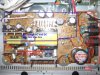
The problem may very well be with the power supply board (the largest of the two light brown or sand colored boards with the yellow transformer on it). stay well away from this board if it is plugged in as it is extremely dangerous.
You will see your 120v mains supply attached to this PSB board (to the power supply board) by means of the silver mains lead and a two wire (two-pin) connection to the PSB. These two wires (the black wire and the white wire) join the PSB in that white two pin socket plug connection. This is where the mains electricity enters the device. They are your two mains AC wires, live and neutral. The danger zone.
Thereafter, the regulated output voltage (12 volts or whatever it may be) exits the PSB via the five-pin to four-pin red and black wires. I suspect everything on the sunny side of that four pin connection is fine and the problem lies in the PSB. It may well be that no or no adequate voltage is leaving the PSB and getting to the rest of the device.
Absent other information, I would begin by reading a book by an experienced engineer about fixing domestic appliances. You should be able to download one for a couple of dollars from Amazon via Kindle.
I would first check the upper voltage specifications of the radial electrolytic capacitors (just by reading the information on the side of each cap) to give you an idea of what sort of voltages you may be dealing with (after the PSB has supposedly done its magic and supplied power to the rest of the device).
They should be relatively low voltages, and though I caution against checking these voltages with a multimeter, if you do so please do so with great caution (though I advise you to instruct a qualified electrician).
So you just may safely be able to check (with a Digital Multimeter) the voltages in play on the circuit board beside the PSB (do NOT try and check the PSB itself when it is plugged in - WAY too dangerous, in fact the entire exercise is dangerous and should not be attempted unless you consider you have the skill to do it. (I caution against it but I am not your keeper).
If you are unable to identify any voltage whatever in the circuit board beside the PSB, that would tend to indicate a fault in the PSB.
If my guess is right, you would then have two main options. First, get a replacement PSB of the correct specifications on Ebay and replace it. That should cost no more than about $30 dollars.
The second alternative, if you are feeling intrepid, would be to consider replacing the radial electrolytic capacitors (not the very large one to begin with) on the PSB obviously after unplugging the device and removing the sand colored circuit board.
I say this because there appears to be writing in Mandarin on the side of the Electrolytic capacitors indicating they were made in China. Some Chinese brands of electrolytic cap are notoriously unreliable, often lasting only a couple of years at most. Although they all seem to look ok, if they are made for example by Capxon (I think that is the name) I would replace them all, as it will only cost a few dollars to replace them and it is an interesting weekend project.
The radial electrolytic capacitors on the power supply board are cylindrical with aluminium tops and most appear to be black though some may be purple or blue etc. They will be marked with the upper voltage limit on the side of each one (that is, how high the voltage can go before they will definitely fail) as well as their capacitance in micro-farads (uH) (how much charge they are designed to store and release). The values will probably range from about 10,000 uF for the massive cap on the PSB to perhaps 10uF and 47uF through to 3,330 uF elsewhere. Measuring instruments are available to check whether capacitors have failed or not but they tend to be very expensive and often you must remove the caps from the board before testing them. You could begin by removing one or two you are most suspicious of and then checking the knowledge base on this site to learn how to check them with various instruments (very basic tests can even be done with a multimeter though they are not very accurate).
Again you should not attempt any work on mains equipment without being extremely cautious and only if you consider you have the appropriate expertise and safety awareness.
If you decide not to proceed, why not remove some of the components for other projects such as the DVD drive and maybe some of the more exotic components.
Kind regards
Edit: try and get hold of a mains rated multimeter with clip on connectors so you do not have to actually touch anything if you decide the plug the device in to test voltages. Keeping your hands away from the device, and certainly keeping both hands away from it at once, is key because electricity might pass through your heart and could kill you if you use both hands.
Edit: Note that electrolytic capacitors (unlike several other types of capacitors such as ceramic capacitors) are pole sensitive, meaning that they must be connected the right way round (they have positive and negative terminals). Getting them the wrong way round means they will not work. they are marked with a negative sign on one side to help distinguish which way round they go. New ones normally have a slightly longer wire on the positive side but as these caps are already attached to your circuit board they will have had their wires clipped.
Edit: Also I would replace the glass fuse beside the power terminal input on the PSB as who knows, it may have blown and could be an easy fix (replace with an identical fuse)