Maker Pro
Maker Pro

Simple Uninterrupted Power Supply Circuit

Hi guys.

I've had great success with my simple NiMH charging circuits, so I thought I would take it a step further and make something that I've been in need of: a general purpose UPS / Powerbank for my Raspberry Pi (which, as a bonus, can double as NiMH charger.)

Requirements are:
1. When plugged into AC, power the Pi and charge batteries simultaneously.
2. When no longer receiving AC power, power is supplied via the batteries.
3. Reverse current protection for the "AC" power supply (as this may be a solar panel and not AC sometimes).

Attached is a circuit that I think meets these criteria, but I wanted to post it here and get feedback just in case I'm doing something obviously wrong.

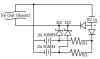
The two unlabeled diodes should prevent reverse current into the power source, and the lower one also serves to drop the voltage down to a more appropriate range for charging the NiMH cells.
R1 and R2 limit the current into the NiMH cells to a safe range, around C/20 or lower. I might make the resistance select-able for when I want to charge quicker or larger capacity batteries.
D2 and D3 prevent current from taking an alternative path into the NiMH cells and frying them when a powersupply is connected, but allow the NiMH cells to provide power to the output when the powersupply is not active.
D2 and D3 should not short the supply to the NiMH cells because the voltage on the main power rail would be higher due to the forward voltage drop (I think).

Have I got all of that correct?
 

Attachments

  • ups-schematic.png
    ups-schematic.png
    12.7 KB · Views: 106
Last edited:

(*steve*)

¡sǝpodᴉʇuɐ ǝɥʇ ɹɐǝɥd
Moderator
It will probably overcharge your batteries (and/or be slow to recharge them), and we normally draw the +ve rail at the top. Is there a reason all your diodes aren't specified as schottky?

Apart from that, it looks reasonable.
 
It will probably overcharge your batteries (and/or be slow to recharge them), and we normally draw the +ve rail at the top. Is there a reason all your diodes aren't specified as schottky?

Apart from that, it looks reasonable.

Thanks! I do realize that with this circuit I'll either have very slow charging or over charging if left plugged in indefinitely (as a UPS would be). I actually have 3 possible solutions for this:

1. Selectable resistance on R1 and R2. Perhaps C/10 for charging while monitored, and C/30 or C/40 for when I just leave it plugged in as a UPS.

2. Drop the voltage down to around 3V using an LDO Regulator before the NiMHs. This will give me a tapering off current as the cells increase in voltage, allowing me to start charging as high as C/5 and end charging around C/20. I've already built a circuit that does this and works reliably.

3. Use a shottky and 3x NiMH for a similar tapering result, as the voltage range is much "tighter", but this would be less reliable compared to #2 because the charging current would be more significantly affected by input voltage which could range from 5.2V to 4.8V or below.

The main reason I'm using regular diodes instead of Schottky before the NiMH is to drop the voltage closer to what you'd normally charge NiMH at, and also create a very small tapering off effect that I described above. This brings the input voltage down from 2.5V / cell to 2.1V per cell (if we ignore the resistor which should drop the remaining voltage anyway), which is still a bit high, but I've seen simple commercial chargers that do the same. I will most likely just add an LDO Regulator as described above to remedy all of these problems, though.

PS. I didn't know that +ve is drawn at the top by convention. Actually, I don't know anything about conventions when drawing circuits besides the main symbols. As you can see, I didn't even know how to draw the 5V Boost regulator or USB inputs / outputs. Always looking to learn, though :)
 
Last edited:
1. When plugged into AC, power the Pi and charge batteries simultaneously.
2. When no longer receiving AC power, power is supplied via the batteries.
A simple relay can do that, driven from your power input. when power is present it can direct it to the pi and charging circuit. when power is removed the contacts can route battery power to the pi.

:)
 
Energizer and a Japanese battery company recommend a trickle charge current of C/40 or less for good battery life. Your C/20 causes a long charging time and a fairly high overcharge current.

The Ni-MH manual from Energizer shows that the battery voltage drops when fully charged which will cause your trickle charge current to be even higher than you think. That is why a charger IC detects the voltage drop as being a full charge then it turns off the charging.

You're right that C/20 is probably too high for leaving it plugged in as a UPS indefinitely.

However, the voltage drop issue only occurs at fast charging rates of about C/5 or above. At C/10, the effect is almost undetectable. So, there's no chance of this happening, because my charger quickly drops down to around C/10 where it spends most of its time charging.

I've already built and tested this circuit with a few different brands and similar capacity NiMHs, and they all reliably terminate at a low charging current of around C/20 or less and stay there. Even if they did attempt to over charge, this would cause the voltage to spike up to 1.5V or 1.6V before dropping, and my charger is designed to bring the current down to safe levels at 1.4V, so there's no way that can even happen.

There are some nice charts of NiMH charging curves at various currents and voltages detailing this in my previous thread, but essentially, as long as you don't exceed C/10, a NiMH cell will finish charging no higher than 1.4V and will not exhibit any detectable voltage drop or temperature change. I think this is actually a much softer and safer way to charge NiMH rather than forcing a constant, fixed current through them as long as you don't miss-match the charger with batteries of lower capacity than it is designed for.
 
Last edited:
Top