Hi Guys!
I am trying to create a very simple circuit using the PIC18f45k20 microcontroller whereby when power is applied to the PIC a welcome message appears on the LCD, when a button is pressed it sends a pulse to a relay to turn a motor on (Port RB4) When the button (RB4) is pressed again the motor stops running. I have attached the circuit diagram
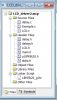
I am coding in MPLab using the C18 compiler. I have attached the set up project window and I am a bit unsure how to finish the code.... Here's what I have got so far....
Any help would be incredible!!!
I am trying to create a very simple circuit using the PIC18f45k20 microcontroller whereby when power is applied to the PIC a welcome message appears on the LCD, when a button is pressed it sends a pulse to a relay to turn a motor on (Port RB4) When the button (RB4) is pressed again the motor stops running. I have attached the circuit diagram
I am coding in MPLab using the C18 compiler. I have attached the set up project window and I am a bit unsure how to finish the code.... Here's what I have got so far....
Code:
/** C O N F I G U R A T I O N   B I T S ******************************/

#pragma config FOSC = INTIO67, FCMEN = OFF, IESO = OFF                       // CONFIG1H
#pragma config PWRT = OFF, BOREN = SBORDIS, BORV = 30                        // CONFIG2L
#pragma config WDTEN = OFF, WDTPS = 32768                                    // CONFIG2H
#pragma config MCLRE = OFF, LPT1OSC = OFF, PBADEN = ON, CCP2MX = PORTC       // CONFIG3H
#pragma config STVREN = ON, LVP = OFF, XINST = OFF                              // CONFIG4L
#pragma config CPB = OFF, CPD = OFF                                         // CONFIG5H
#pragma config WRT0 = OFF, WRT1 = OFF, WRT2 = OFF, WRT3 = OFF                // CONFIG6L
#pragma config WRTB = OFF, WRTC = OFF, WRTD = OFF                            // CONFIG6H
#pragma config EBTR0 = OFF, EBTR1 = OFF, EBTR2 = OFF, EBTR3 = OFF           // CONFIG7L
#pragma config EBTRB = OFF                                                  // CONFIG7H


/** I N C L U D E S **************************************************/
#include "p18f45k20.h"
#include "stdio.h"
#include "delay.h"
#include "LCD.h"

/** D E C L A R A T I O N S ******************************************/


void main (void)
{
    OSCCON = 0b01110010;        //8 MHz
    TRISD = 0b00000000;        // The Output to pin D is the Motor
    TRISC = 0b00000000;        // The Outputs to pin C go to the LCD
    TRISB = 0b00000000;        // The Outputs to pin B go to the LED's
    TRISA = 0b11111111;        // The Inputs to pin A come from the LDR's, SW1 and the FSR.

    stdout = _H_USER; //Set to user-defined output stream via _user_putc

    lcd_init(); //Initialize the LCD
    send_cmd(0x0C); //Turn off cursor

    set_cursor(1, 1); //Set cursor to row 1, column 1
    printf("EvilCanEvil");

    set_cursor(2, 1); //Set cursor to row 2, column 1
    printf("Press Go to crush Cans!");


}

{
    TRISD = 0b10111111;         // PORTD bit 6 to output (0);

    LATDbits.LATD6 = 1;        // Set LAT register bit 6 to turn on Motor

}
Any help would be incredible!!!