Maker Pro
Maker Pro

series battery

Hello, I connected an amperometer to the opposite poles of two 1.5 V batteries not connected in series but there was no current flow, why ? shouldn't opposite charges attract each others ?

thanks
 

davenn

Moderator
how is the circuit connected ?
the way you have worded your comment doesnt quite make sense sorry

draw a pic and show us how its all connected

Dave
 
they are connected in this way, i think it has no sense what i did but i don't understand the principle of series connected voltage sources :(
 

Attachments

  • crcre.png
    crcre.png
    10.9 KB · Views: 374

(*steve*)

¡sǝpodᴉʇuɐ ǝɥʇ ɹɐǝɥd
Moderator
There is no circuit. Also the voltmeter isn't going to ever read anything significant even if there is.

Let's take a step back. What are you actually trying to do?
 

davenn

Moderator
OK we will assume that you are just experimenting and learning how to take Voltage and current measurements.
As steve said, ( and I suspected this from your first post) you wont measure any Voltage or current with the way the circuit is at present. The circuit isnt complete

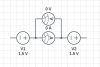
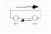
Have a look at this circuit I have drawn for you and how the Ammeter and Voltmeter are connected.

attachment.php


Note the circuit is complete from the bottom battery to the top one, then through the Ammeter, through the 10 Ohm resistor load and back to the other terminal of the bottom battery.

The Ammeter must be in series with the load and the Voltmeter is used to read the Voltage across the load.
NOTE -- ALWAYS have a load in series with the Ammeter and the battery(s) else the Ammeter will try and read the full current flow that the battery(s) are able to supply and this may damage your meter.

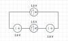
in this circuit we have the Voltage = 3V 2 x 1.5 Volt batteries in series.
We have the load resistance 10 Ohms so we can work out the current flowing in the circuit and see if that equals what we read on the meter

I = V/R ( Voltage / Resistance) = 3V / 10 Ohms = 0.3 Amps ( 300mA)


cheers
Dave
 

Attachments

  • Meter connections.GIF
    Meter connections.GIF
    2.9 KB · Views: 207
Last edited:
Basically i'm trying to phisically understand how the total voltage of batteries hooked in series is the sum of their single voltages.
If the electrodes of a Galvanic cell are immersed in the electrolyte shouldn't the catod continously emit electrons and be a current flow in my last circuit ?
 

(*steve*)

¡sǝpodᴉʇuɐ ǝɥʇ ɹɐǝɥd
Moderator
Imagine the battery is like a pump. the wires are like pipes.

If the pipes are not connected, the pump will have no water to pump and will run dry.

Connect the pipes in a circuit and the pump can push water around.

A battery doesn't create electrons it just takes them from one side and pushes them out the other side (with more pressure, or voltage)
 
A battery doesn't create electrons it just takes them from one side and pushes them out the other side (with more pressure, or voltage)
I can figure out the electrons way when I only use one battery because there is one positive and one negative, but what way they do in two batteries in series ?
 

(*steve*)

¡sǝpodᴉʇuɐ ǝɥʇ ɹɐǝɥd
Moderator
You mean "cell" not battery. A battery is simply a collection of cells.

You can buy 1.5V cells, and 9V batteries. Te 9V battery has 6 1.5V cells in series.

Placing cells in series is like putting pumps in series. Each gives a bit of a boost to the pressure. So 2 pumps can push twice as hard as one, and 2 batteries can push twice as hard as one. That push defines how far up that potential we can go. In the case of pups, it's a distance, in the case of batteries it's a voltage.

So double the batteries, double the voltage.
 
That is the correct direction of flow for electrons. But current is the flow of charge. Since electrons are negatively charged, the current flows in the other direction.

Bob
 
Let's say you have two guys who can each throw a ball 30 feet high. You position the first guy on the ground, and the second on a 30 ft high platform. The first guy throws the ball to the second guy. Then the second guy throws the ball 30 feet up. How high did the ball go?

Bob
 

(*steve*)

¡sǝpodᴉʇuɐ ǝɥʇ ɹɐǝɥd
Moderator
shouldn't voltages be like this ?
there is something I still can't get :(

Yes, you will get exactly what you say in that case. But it is only because you are using the voltmeters in a very non-standard way.

It's a bit like (in bobk's case), you measuring the 30 feet each thrower achieves with separate measuring tapes.

OK, both measure 30 feet. Is the total 30 or 60 (or indeed could it be zero)?

(your circuit is actually worse than that because your voltmeters are measuring -- in a manner of speaking -- current)
 
I don't think you get that result unless two voltmeters have the same impedance, do you?

bob
 
Last edited:

davenn

Moderator
Ok but a current is associed with a voltage

yes, but they are measured in different ways
Voltage is measured across ( in parallel) the power supply
Current is measured in series with the supply .... as you have shown with the lower meter
its a poor Voltmeter trying to read current

Go back to my post, post #5 and see how the 2 are connected in the pic I drew for you


Dave
 

(*steve*)

¡sǝpodᴉʇuɐ ǝɥʇ ɹɐǝɥd
Moderator
I don't think you get that result unless two voltmeters have the same impedance, do you?

Assume two identical 1.5V cells and two identical voltmeters set to the same range...

scientifico, the fact that this is a concern is an indication that the voltmeters are being used (at the very best) incorrectly.

Voltmeters should *never* be connected in series with the load. If removing a voltmeter opens the circuit, you're doing it wrong. A perfect voltmeter has an infinite resistance (it is essentially an open circuit). In this circuit perfect voltmeters would both read zero.
 
Top