Maker Pro
Maker Pro

Sealing a coax end from RFI leaks

Hi i'm new to the forum, Thanks for any help you can give. My question is, I have project that uses a coax cable to transmit a signal to a decoder box used in lap counting for RC Cars. When I use the factory coax cable that came with the system , I plug it in via BNC connector to a decoder box and it registers zero noise level on the decoder box. When I put the coax I am supplying on the decoder the noise level rises to 40. The only difference is the factory one is sealed in some black hardened plastic and my cable end is exposed. What stuff can I use to seal up my coax end preventing this noise from entering the decoder box via the coax end.
 
I'm also not sure what you are saying. How does a coax cable detect the cars? If your coax cable is exposed at the end, I mean what is that about? Any cable I ever see connects to something on either side (unless it's an antenna).
You'll have to carefully open up the plastic end on the factory cable, to see what is really in there (perhaps a terminating resistor?).
 
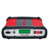
Thank you guys so much for taking the take to respond to my questions. I will post some stock pictures of the components.

Here's how things work. We have the decoder box. That is connected to a computer and run using a specific RC Car software program for scoring. A coax connects to the back of the decoder and runs approximately 50 foot in my case to a single wire that is buried in the track.The wire approximately 40 foot in length makes a loop, so it goes across the track lane and comes back. Each end is connected to the coax, One to the center and one to the outer part of the coax. When the cars cross this loop in the track their laps times are recorded. So you have the coax going to a single strand of 16 gauge wire in the track making a loop.

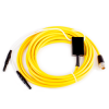
Okay these single loops/coax cost 250 bucks and I want to just make my own, As you can see in the picture with the yellow coax at the.end there is a little black box, which is actually some hardened plastic hiding whats in the there. It has the two wires coming out that I connect to the 16 gauge wire in the track. The decoder has a noise level indicator. When I plug in the yellow coax to the decoder WITHOUT the 16 gauge loop wire connected there is a zero reading on the noise level. When I plug in the coax cable that I am making the noise level is in the 40's. When noise starts getting high it start miss counting, so I need zero noise before the loop just like the 250 stock version has.

I have dissected the black box and the was a tiny cooper coil in there. Reading what a termination resistor is may be exactly what I need. I do also know this. The coax not connected to the 16 gauge scoring loop need to read 100k ohms. I added a 100k ohm resistor to the end of the coax and did get the 100k Ohm reading but have way too much noise, unlike the stock factory cable.

I also have included a PDF on how to test the factory loop. I have the 470 ohm loop in the ground tested and working, I need to figure out the coax part.

thank you guys for helping.

Here are some picturesa2e8689dd4dba04ff035385972c355e4_normal.png Decoder.png Loop Motorized.png
 

Attachments

  • Electrical_test_passive_detection_loop_v1.pdf
    210.7 KB · Views: 96
Ok, here are my thoughts now. The decoder box is actually feeding in some higher frequency signal. I assume there is metal in the cars. The decoder is measuring inductance of the loop (just like at traffic lights). As the cars pass over the loop, they temporarily change the inductance and that's what the decoder is picking up.

You need to focus on that black box. You said the only thing that was in there was a little coil? You didn't say there was a resistor in there, but then you mention 100kOhm. Let's get more detail on what's in there.
 
thank you. The cars actually have transponders in them with a 7 digit number, pictured above. That's how each car is scored separately. Although it does not happen, 20 or more cars could cross the loop at the exact time and they would all be counted/scored. The little black plastic box on the end of their coax had a small copper coil wrapped around a small black ring inside. When I say small I mean as small as the cable end. I had to take a dremel and grind away slowly the black plastic stuff or what ever it was to expose only the coil and the two wires connected to the coax. It was not a clean enough dissection to get a good description on the coil. I have looked but never saw one that small. There was nothing else in there.

So what ever they have done to the end of the coax kills any noise from feeding back into the decoder and it makes the ohm reading 100k on that coax My open end cable produces noise in the decoder before I get to the loop part, their's does not. I need to kill that noise and make it read 100k ohm I only tried the 100k ohm resistor in hopes that I would get lucky. The cable will read 100k ohm when I connect both sides with the resistor but there is still too much noise present.

thanks everyone for taking their time to help me. I really appreciate it and look forward to each response.
 
You could try posting pictures. So are you saying the center conductor of the coax went around a black ring and then it connected to the shield of the cable? It's hard to understand it without know which wire goes where. Imagine a subway station map that just shows the stations but doesn't show how they are connected. How would you know how to get from A to B you know.
 
I will have to dissect another one and get some pictures. This is why my main question was, do they make a RFI blocking epoxy. Again thank you for you time.

Did you take a look at that pdf that more explains how it's set up?
 
haha I am on that site already. That's a good thread, but the factory has done it will so little. I've tried some of those and still have the noise that is not acceptable for a reliable system.

Follow this link if you want to see what the track and cars.
 
Top