Maker Pro
Maker Pro

review my design and let me know if anything will go wrong

this is a simple circuit yet as it uses 220 ac volts i'm think the smart thing is to ask experts if there is anything wrong with it before plugging it in

i've a laser sensor with a relay that switches off if the beam isn't recieved
a timer relay (delay on) which i use to turn the circuit on for certain amount of time
a contactor which i use to first drive the load and second to latch the timer on for
as long as the delay as cause the laser sensor only give me pulse

please review my design and let me know if anything will go wrong
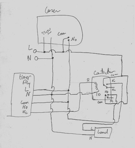
IIE7qM2.jpg

uJSBD86.jpg
 
this is a simple circuit yet as it uses 220 ac volts i'm think the smart thing is to ask experts if there is anything wrong with it before plugging it in

i've a laser sensor with a relay that switches off if the beam isn't recieved
a timer relay (delay on) which i use to turn the circuit on for certain amount of time
a contactor which i use to first drive the load and second to latch the timer on for
as long as the delay as cause the laser sensor only give me pulse

please review my design and let me know if anything will go wrong
IIE7qM2.jpg

uJSBD86.jpg
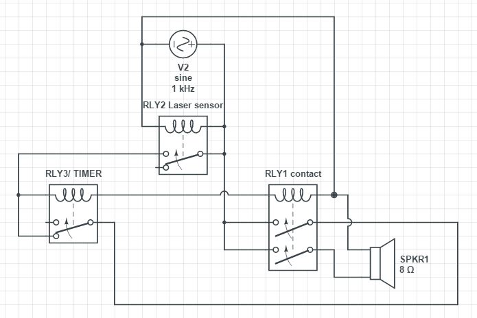
Fist question being... Why is RLY1 and RLY3 in series with each other and RLY2 is not?
Are you using 110V relays as well? Are these relays meant to operate on AC?
RL3 is not doing anything either...
When RLY2 turns on, both RLY3 and RLY1 will get switched on at the same time.
 
Fist question being... Why is RLY1 and RLY3 in series with each other and RLY2 is not?
Are you using 110V relays as well? Are these relays meant to operate on AC?
RL3 is not doing anything either...
When RLY2 turns on, both RLY3 and RLY1 will get switched on at the same time.
all relays are 250v holding 220v (all ac), rl3 is a timer, it's suppose to switch to the NO after 60 second of buzzing only using a pulse so it would turn on the contact and the contact would latch the relay input so it would stays on, when the rl3 switch the latch will be gone so is the laser signal (long ago) so both rl2 and rl3 would switch off (that's the idea anyway)

and that's how i want it to work, i was doubting myself as if there is any short circuits after or before switching, it's why i'm mainly asking before i plug it in
Well.. current configuration.. The laser sensor goes off and both the RLY1 and RLY3 may not even be triggered because they require 440V if they are in series like you have drawn..
 

hevans1944

Hop - AC8NS
this is a simple circuit yet as it uses 220 ac volts i'm think the smart thing is to ask experts if there is anything wrong with it before plugging it in
There is a lot wrong with it. I would not plug it in.

You should be most concerned about the 8 Ω loudspeaker being connected across the 220 V AC power line L and N terminals if RLY1 somehow became energized. That whould make for a rather nice explosion, perhaps melting the NO contacts on RLY1 and blowing the voice coil out of the loudspeaker before a circuit breaker tripped.

And where does that V2 1 kHz sine source come from? It isn't shown on your hand-drawn circuit.
 
Top