Hi,
I have a circuit meant to control AC solenoids, and using TRIACS to do so, and I'm trying to externally control it.
Its seemed fairly simple so I started measure voltage and make sens of the board, and as soon as i connected a scope the whole thing blew up , So...I got a replacement board and made a full schematics of it.
It uses an atmega8, I might be able to reprogram it to my purpose or replace it with an arduino chip, either way the impotent part is to understand how the triacs control the coils, and how not to blow the board agian.
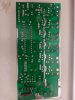
the board takes a 220V input, and controls 4 coils, the board allows intensity and rhythm control, my guess so far is that an pulse at the base of the 2222a somehow determines the amplitude of the ac voltage and 0 is off... not sure..
but before i try to poke the board again id appreciate any advice, and some DO's And DONT's for the board.
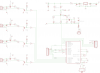
here is a LINK to the eagle schematic all the values and part numbers are accurate. U3 is just a low voltage detector, TH1 looks lke a cap but behaves like a short, not sure what it is.., R999 is a fix to the board that looks like it was done manually after manfuactering, feel free to ak any question, verfy anything, request tests or mesures...
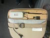
attached some pics


thanks! atntias
I have a circuit meant to control AC solenoids, and using TRIACS to do so, and I'm trying to externally control it.
Its seemed fairly simple so I started measure voltage and make sens of the board, and as soon as i connected a scope the whole thing blew up
, So...I got a replacement board and made a full schematics of it.It uses an atmega8, I might be able to reprogram it to my purpose or replace it with an arduino chip, either way the impotent part is to understand how the triacs control the coils, and how not to blow the board agian.
the board takes a 220V input, and controls 4 coils, the board allows intensity and rhythm control, my guess so far is that an pulse at the base of the 2222a somehow determines the amplitude of the ac voltage and 0 is off... not sure..
but before i try to poke the board again id appreciate any advice, and some DO's And DONT's for the board.
here is a LINK to the eagle schematic all the values and part numbers are accurate. U3 is just a low voltage detector, TH1 looks lke a cap but behaves like a short, not sure what it is.., R999 is a fix to the board that looks like it was done manually after manfuactering, feel free to ak any question, verfy anything, request tests or mesures...
attached some pics
thanks! atntias