Maker Pro
Maker Pro

Resistance range to output voltage range

Hi all,

I'm a newby here and only have a fairly basic electronics knowledge.

What I am wanting to know is how to convert a variable resister to a variable voltage output, very low current draw as it just runs an electronic fuel gauge.

The output of the sender varies from 10 ohms (empty) to 149 ohms (full).
The input to the gauge needs to be 0.1v empty and 4.5v full.
Supply voltage is a regulated 12VDC.

I played around with a resistor calculator but couldn't find that happy medium.

Can any one help me with this? Can this be done simply or will it require something a little more elaborate??

Thanks in advance!

Matt
 
As you have determined, you cannot get this relationship with just a voltage divider.

Normally, one would use a constant current source to convert a resistance into a voltage linearly. But your two points indicate that that would not work either.

At the high end: I = V / R = 4.5 / 149 = 0.03 = 30 mA
At the low end: I = V / R = 0.1 / 10 = 0.01 = 10mA

Can you get some more points to see if it is indeed something like linear maybe with the low end being off a bit? I.e. can you get the voltage and resistance needed to read 1/2 full?

Bob
 
Well a 248R resistor will give 4.5V on full and 0.465V on empty, which will render 10% at the low end unusable, if the meter is linear. The other thing to watch is the heat generated as that will generate 0.5watt on empty which is when there are the most fumes around.
 
Hey guys, Thanks for the responses so far.
For the fuel sender the resistances are as follows:
Empty - 10
1/4 - 40.5
1/2 - 66
3/4 - 95
Full - 149

For the voltages, all I have is:
Empty - 0-0.1
Half - 2.2-2.8
Full - 4.1-4.5

Hope that is to some assistance?

Matt
 
yeah, I imagine that .5 watts would be too much for the sender, and as mentioned it is located inside the fuel tank......
 
yeah, I imagine that .5 watts would be too much for the sender, and as mentioned it is located inside the fuel tank......
Ill play around with some numbers in my head... I'm thinking of a wheetstone bridge... perhaps someone can chime in about it's plausibilty
 
How about using a little PIC and reading the voltage drop across the sensor(ADC) and then use PWM to drive the meter.It will be a simple circuit and easy to calibrate. This would allow a much lower voltage across the sensor(reference voltage can be 1.5v for example would halve the wattage).
 
Last edited:
How about using a little PIC and reading the voltage drop across the sensor(ADC) and then use PWM to drive the meter.It will be a simple circuit and easy to calibrate. This would allow a much lower voltage across the sensor(reference voltage can be 1.5v for example would halve the wattage).
Or you could just read the resistance.
Here are some notes done for a PIC16C622
http://www.microchip.com/stellent/idcplg?IdcService=SS_GET_PAGE&nodeId=1824&appnote=en011113
 

KrisBlueNZ

Sadly passed away in 2015
Fuel gauges aren't linear anyway in my experience. They report less than half full when the tank is half full, to encourage you to fill up without waiting too long. And the sender isn't likely to be perfectly linear because of its design and manufacturing errors. Some non-linearity is sure to be tolerable.

I've graphed your figures from post #4 FYI:
fuel level vs. sender resistance.png
Does the sender have two wires, fully isolated from the chassis, or does it have one wire and the other side is connected to the chassis?

Is the supply voltage only present when the vehicle is running? Or is it present all the time? This affects the amount of current that can be drawn from it.
 
Wow, thanks everyone for the input! I kinda didn't expect much! :)

Gryd3/shumifan50, I have no idea what you are talking about (lol) but I will google up on your suggestions to get my head around it.

KrisBlueNZ, Nice graph! Didn't even think of doing that myself with Excel.
Answers to your questions.
The sender is two wires, independent of chassis/ground.
Power supply is ignition ON only (99% sure), even if not, could trigger it with a relay if required.

Just a bit of background for this.
Fuel gauges in Australian 1979-1987 Ford Falcons use a Capacitive type fuel sender (no moving parts) These are now no longer available and any old stock goes for a small fortune(A$300-A$500) and there are several different types depending on body type (sedan/wagon etc).
Now I'm not a tight ass so as to not buy one for this price. There are other issues with these, the big one, is that E10 fuel plays up in how they read. Petrol has a dialectic property of 2.0, water is 80.3 and Ethanol is 16.2. That doesn't mean a lot to me but what it does mean is that it will read full for 3/4+ of a tank on E10 and then plummets! Not really ideal.
From 1988, Ford changed to an ohm meter style gauge and sender with a float. Since I'm mechanically sound (diesel mechanic by trade) im good in making square pegs go in round holes but not so good in soldering diodes and IC on circuit boards lol.
For a little more background on the older sender have a read here http://www.ozfalcon.com.au/index.ph...-level-display-capacitive-probe/?fromsearch=1

See the attached photos of my car :)
1617600_10202473021760719_393749615_o.jpg

10001063_10202663970934329_266009198_o.jpg


Thanks again for everyone's input!
 
Something that I have come across and might be an easier conversion, you can get an interface that is used to kinda do what I am asking, sort of, bear with me!

Capture.PNG

Now! 99.8% of automotive LP Gas tank gauges have a level sender that works on 0 ohms empty - 90 ohms full.
I wonder if using this might get me closer??

Thoughts??

CP94WIRING.jpg
 

KrisBlueNZ

Sadly passed away in 2015
I don't know about the CP94, CP95 and CP96 boards. If they're cheap, you could buy one and try it. Without seeing a schematic diagram for them, I couldn't say whether they'll work or not.

I could draw up a circuit with about 10~15 components, including an 8-pin IC:
8-pin-dip.jpg
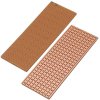
... which you can build up on stripboard:

small-stripboard.jpg

Do you feel confident that you could build it up? I could include links to all components on Digi-Key or Radio Shack. I just want to know whether there's any point drawing up a design.
 
I could definitely build it, not a problem. If I had a list of components and drawing, I could put it together. I just would never be able to design it from scratch lol.

If I had a list, I could walk in to my local Jaycar (www.jaycar.com.au) store and they would get the components it for me.
 

KrisBlueNZ

Sadly passed away in 2015
OK, here's what I suggest.

269385.001.GIF

There's a complete list of Jaycar parts there. The total cost is about AUD 21. You will also need solder, soldering iron, enclosure, wire, etc.

The circuit is a "non-inverting amplifier" using an LMC6482 dual op-amp. This is the most suitable device that Jaycar have. D1 protects the circuit against reversed power supply. U2 is a 7808 regulator that generates a regulated, stable +8V supply for the rest of the circuit. R1 causes about 1 mA to flow through the sender, which produces a voltage at R2 of about 0~150 mV according to the sender resistance. R2 and C1 remove noise from this signal, and U1A amplifies this voltage, relative to the 0V rail, by a factor of around 30 (adjustable via VR1) to produce a voltage range of 0~4.5V at the output, which drives the dashboard meter.

There is no processing performed on the signal (apart from noise removal) so the dashboard meter will respond directly and proportionally to the sender resistance. I think this will be fine for this application, but if an offset is needed, the meter can be offset to the left slightly by adding a resistor of around 1 MΩ between U1 pin 2 and the +8V rail. Use a lower resistance for more offset.

I have suggested 2-pin latching polarised headers for the connections to the sender and the dashboard meter, and a 2-pin polarised shrouded plug/socket combination for the power input. Accidentally interchanging the sender and the meter is unlikely to cause any damage.

You will need to translate the schematic into a stripboard layout. There are several tutorials out there; Google is your friend. Have a decent go at it, and if you get stuck with any specific questions, ask them here.
 
The 10 Ohms at empty is what bothers me. Couldn't we subtract the voltage at 10 Ohms with the op amp to get a 0.1V at empty and adjust the gain to get the full scale value of 4.5V? I think this would improve the circuit.

Here is a modification of the circuitry around the op amp in Kris's circuit that does this.
R6 is the gas-tank sender.

Output is 0.102V at 10 Ohms and 4.48V at 149 Ohms.
A 10K trimmer could be placed in series with R4 to adjust full output to 4.5V.
Also a 0.1uF cap across R6 and R8 would help stabilize it.

fuelgauge.JPG
 
Last edited:

KrisBlueNZ

Sadly passed away in 2015
The 10 Ohms at empty is what bothers me. Couldn't we subtract the voltage at 10 Ohms with the op amp to get a 0.1V at empty and adjust the gain to get the full scale value of 4.5V? I think this would improve the circuit.
I don't think that will be an issue in the big scheme of things; it's only a fuel level meter. But I did consider the possibility:
There is no processing performed on the signal (apart from noise removal) so the dashboard meter will respond directly and proportionally to the sender resistance. I think this will be fine for this application, but if an offset is needed, the meter can be offset to the left slightly by adding a resistor of around 1 MΩ between U1 pin 2 and the +8V rail. Use a lower resistance for more offset.
 
The OP said it should output 0.1V at 10 Ohms for the empty indication. I can see the gas gauge having E marked somewhere above the 0 point so that you can distinguish between empty and meter off. I believe your method will have something like 0.3V output for 10 Ohms, which means it will never indicate empty.


Edited: OK, I see now how a resistor from - input to V+ would offset it as well. So that should be set for 0.1V then the gain set for 4.5V full scale and it works pretty much the same as my circuit.

Bob
 
Last edited:
That is excellent Kris! Thanks for your efforts!!! I did email the company about the interface mentioned, and the wanted about A$80 delivered.
This should, hopefully (depending on my skills lol), work for a much cheaper price and be more accurate!

I doubt I will have a crack at is this weekend, but I will next! I will post up pics of my efforts and results.

Thanks again!!
 
Top