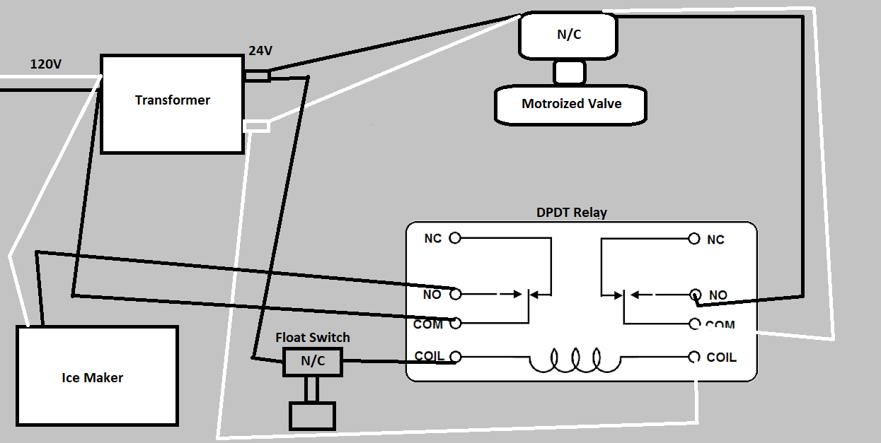
I am trying to create some redundancies for a small commercial ice maker to prevent there from ever being a flood in my garage. The ice melts from the ice bin (which holds around 80lbs of ice) constantly and gravity drains from 3/4" PVC into a condensate pump a few inches away… If/when the condensate pump fails, I plan to have a float switch open, breaking the connection at the DPDT relay and turn off the ice maker (to prevent more ice than what is already in the bin from being created) as well as close the newly installed inline motorized Taco zone/ball valve. Any melting ice/water will then stay in the ice machine bin with the valve closed. The Taco valve would also close in a power outage (being that the valve is N/C) so that the ice did not end up melting and draining with no power to run the condensate pump.
Planned install: The c & w/y terminals on the Taco valve would be wired directly to a 24V transformer. The two end switch terminals on the Taco valve would be wired to one of the common and one of the normally open terminals on a DPDT Relay (which is controlled by a 24V normally closed float switch). When the float switch activates (opens), the Taco valve would close. In the event of a power failure the Taco valve would close. See crappy diagram I made below.
Valve: https://www.grainger.com/product/TACO-Two-Way-12M804
FYI: Ice machine pulls around 5-6amps at 120V. Ball valve does around max .5 amps at 24V.

I was thinking I could improve this design by still using one float switch, but if the float switch ever opens it would essentially 'trip' the circuit (closing the ball valve and turning off the ice machine) and require a manual reset. This really seems ideal to me as someone would have to be present to inspect why the float switch was triggered... I have absolutely no idea on how to best implement this (with my limited electrical expertise). This would be especially useful in a power outage... Lets say all 80lbs of ice melted (about 10 gallons of water). When the power comes on, I fear the condensate pump would have trouble keeping up with a mass flow of water (although it is a 270GPH pump with 1G tank). My assumption is there would be several 'trips' of the float switch as the pump worked to remove all the water, and maybe even the possibility of some leakage, overflowing as I believe the valve takes 5-6 secs to open/close (so it will take some time to react as the condensate pump tries to expel the water...
So I came across this thread today and I thought this would be a really cool solution... But then I took a closer look, and from my limited expertise it appears that this circuit would need a manual press of the button every time the power went out or possibly even flickered... Is that right? I was hoping for a solution where ONLY the opening of the float switch would require the manual reset button to be pushed. I don't want to be away from home and end up having my ice maker turned off, only to have all my ice melt just because of a brief interruption in power.
Thread:
https://www.electronicspoint.com/forums/threads/reset-button-for-relay-switch.281324/
Looks like the same circuit described here:
https://chicagosensor.com/HighLowLevelApps/
Planned install: The c & w/y terminals on the Taco valve would be wired directly to a 24V transformer. The two end switch terminals on the Taco valve would be wired to one of the common and one of the normally open terminals on a DPDT Relay (which is controlled by a 24V normally closed float switch). When the float switch activates (opens), the Taco valve would close. In the event of a power failure the Taco valve would close. See crappy diagram I made below.
Valve: https://www.grainger.com/product/TACO-Two-Way-12M804
FYI: Ice machine pulls around 5-6amps at 120V. Ball valve does around max .5 amps at 24V.

I was thinking I could improve this design by still using one float switch, but if the float switch ever opens it would essentially 'trip' the circuit (closing the ball valve and turning off the ice machine) and require a manual reset. This really seems ideal to me as someone would have to be present to inspect why the float switch was triggered... I have absolutely no idea on how to best implement this (with my limited electrical expertise). This would be especially useful in a power outage... Lets say all 80lbs of ice melted (about 10 gallons of water). When the power comes on, I fear the condensate pump would have trouble keeping up with a mass flow of water (although it is a 270GPH pump with 1G tank). My assumption is there would be several 'trips' of the float switch as the pump worked to remove all the water, and maybe even the possibility of some leakage, overflowing as I believe the valve takes 5-6 secs to open/close (so it will take some time to react as the condensate pump tries to expel the water...
So I came across this thread today and I thought this would be a really cool solution... But then I took a closer look, and from my limited expertise it appears that this circuit would need a manual press of the button every time the power went out or possibly even flickered... Is that right? I was hoping for a solution where ONLY the opening of the float switch would require the manual reset button to be pushed. I don't want to be away from home and end up having my ice maker turned off, only to have all my ice melt just because of a brief interruption in power.
Thread:
https://www.electronicspoint.com/forums/threads/reset-button-for-relay-switch.281324/
Looks like the same circuit described here:
https://chicagosensor.com/HighLowLevelApps/
