Maker Pro
Maker Pro

Repairing a depth sounder - LPC1113F/202 ARM Cortex-M0

Hello,
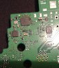
I am repairing Garmin GPSmap 547xs chartplotter / depth sounder where sounder portion stopped working. I have pinpointed the problem to LPC1113F/202. Manufacturer has no heat sink on it and mine heats up to over 100C in seconds. Datasheet suggested total power consumption not more then 1.5W. I have measured 3W to 3.5W on mine.
1 - Am I right to assume that LPC1113 is done for?
2 - Can I just replace LPC1113F/202 or does it require some kind of programing?
3 - How can I test if the rest of the circuit isn't responsible for frying the micro-controller up? (Input voltage is 3v and I have not measured anything over 3V coming to it)
I have removed LPC1113F/202 as I am worried that it may damage the rest of the unit. I can still use the chartplotter thou.
Sorry, my knowledge of digital electronics is zero but I do play around analog stuff a bit.
Really appreciate your help!
 
1- Yes. (Sometimes the only way to find one of those annoying board shorts is to switch on and blow the faulty component off the board - carefull how you do this though ;))

2- Doesn't look like it, as it has on-board flash program memory. There might be a sticker on the cpu with numbers on it - indicating firmware type, date and version. You're more than likely bound to the supplier in this regard.

3- When things cook badly, it's best to check the whole pcb. Your best pointers will be burn marks on the pcb, cracked solder joints are a problem (examine solder connections with a magnifying glass), and also use your nose - Sniff around the board, you'll quickly be able to isolate problem areas (bad smell).

3- Also sounds like this system is on a boat. Boat power supplies are notoriously 'noisy' - check the power input filters to the Garmin. Any high frequency spikes can go right through 'worn' filters onto the digital power supply rails. It sounds like this has happened wrt the LPC1113.

Once the pcb is checked out and looks ok, you could probably get away with placing an 'un-programed'/blank cpu into the socket.
On startup the cpu (theoretically) should remain in the reset state until configured (if the designer has done a proper job), but as no configuration will take place, it should be ok.

Alternatively find the RESET pin on the cpu and hold it in the reset active state. (small soldered wire - usually to DGnd - digital ground)

Post some high res pics of the cpu and pcb.
 
Last edited:
Thank you for your help, I really appreciate it.
I did remove that LPC1113 from the pcb by grinding it off. o_O I could not get it to de-soldered and didn't want to risk damaging the board. Grinding if off with a dremel worked surprisingly well. I took it down to copper and cleaned up what was left with my soldering iron.
Everything else looks good, no cracks, burn marks or smell. To me it really looks like a planed obsolescence case. As it has no cooling but the pcb...
If I can not repair the depth sounder function I would like to still be able to use the plotter. After I have removed that micro-controller everything else powered right up. Nothing heats up out of ordinary and the unit takes 7W (down from 10W)
The replacement chip is on it's way so I'll update you on the progress when it arrives.
I forgot to take photos before or after but I did take a shot while I was trying to take that chip out with my soldering iron. (You can see some flux I put along the edges...)
 

Attachments

  • 2020-12-29.jpg
    2020-12-29.jpg
    502.9 KB · Views: 6
The small leads on that cpu make it difficult to extract off the pcb.
If the chip leads are exposed you can get one of those fine side cutters especially made for this purpose.
You then snip the lead, extract the chip and it's then easy to remove the leads on the pcb.

Otherwise a 100Watt (or 50Watt) soldering iron would work well to get it off
You place a large blob of solder on the iron and hold it on top of the chip.
At intervals use a chip suction extractor to try remove it, or a pair of tweezers.
The chip will eventually move and you have to be carefull not to burn the board and solder pads.

You then use 'solder wick' to clean up the solder pads.
This is just a fine copper mesh in a wired format and is effective in cleaning solder pads.
 
Once the pcb is checked out and looks ok, you could probably get away with placing an 'un-programed'/blank cpu into the socket.
On startup the cpu (theoretically) should remain in the reset state until configured (if the designer has done a proper job), but as no configuration will take place, it should be ok.

Alternatively find the RESET pin on the cpu and hold it in the reset active state. (small soldered wire - usually to DGnd - digital ground)
I have finally replaced the cpu. Had to wait a bit for the chip to arrive. Soldering went on easy, using soldering fan...
The unit powered up and works as before. Meaning:
1 - GPS, navigation, screen and controls work as suppose to.
2 - CPU is not overheating
3 - There is no voltage on the output sounder stage. Transducer is not getting the voltage.
This gets me thinking that I might need to try ColKlonk's suggestion with the Reset pin. What I am not clear about is how long do I need to have a jumper on reset pin. Is there anything else I need to do?
Really appreciate your help.
 
I'd imagine that cpu chip you got from the suppliers is already got the 'firmware' (program) on it.
This sounds like it as you have screen and other things working ok.

I stand under correction, but I'd imagine the transducer/driver stage(s) are blown.
These are probably high voltage FETs, maybe a few of them in a certain configuration. There's probably a fuse attached to this section as well.

There is usually an opto-coupler (for isolation) driver stage before the FET's and you might find one or more of these components are blown.

Also check the tranducers/driver stages for damage and resistance. This (all the above) depends on what type of transducer (check the datasheets) as there are various types.

Any pics of the transducers and pcbs that drive the transducers.
 
I'd recommend that the state of the boat battery and charging system be checked. Also if there's an internal regulator. Otherwise there might be a repeat performance.
 
Top