Hi sorry if this is a bit newb and sorry it's so long, I just wanted to get everything down...
I'm building a basic toy device with a simple PIC/servo/button/led type circuit. For the purposes of this, the circuit can be considered a black box, connected to a battery of 3-5V. It is a fairly low drain circuit (250mA peak, about 50mA average). Battery life is not crucial, but I'd like to get a few hours at a time. I've powered circuits using mains DC and removable batteries before, but I want to make this a rechargeable device, with the battery semi-permanently fixed in-situ. I don't want to remove the battery to charge it, instead it will be charged by plugging in a power supply. I don't mind if the circuit is powered during charging or not, but if it is, it needs to be safe for my PIC (my circuit already includes a smoothing capacitor and VR though)
What I have so far (and would like to use, as they're already in the parts box):
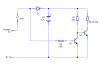
My Circuit
Simple 9V DC power supply (not a battery charger)
Power connector, 3-pin (so I have a connection that opens when the jack is plugged in, if you know the type I mean?)
5V Voltage Regulators (7805s) for my main circuit, and charging if necessary
Whatever resistors, caps, etc I need...
Stripboard for my circuit board.
Basic skills...
What I don't have yet, but can/will get:
Some kind of battery pack
Some kind of charge management IC (I can breakout a SO-23 or whatever, so size/type is not important)
or...whatever other circuitry I need to charge the battery.
Whatever datasheets...that I'm usually able to follow.
What matters to me is safety, ease of construction, and circuit size, with cost being the least important.
What I need to know and can't seem to fathom (too many results rather than too few!) is what my best option is for battery type - and what I need to do in my circuit to ensure that, when plugged in, the power supply will safely charge the battery, and/or power the circuit while that is happening, and give charging state feedback via an LED. As you can tell, I am fine with building circuits, and fine with programming, I just can't seem to find any decent guide to building this kind of circuit.
It seems to me that a 1-cell Li-Po would work, and I can find lots of cheap Li-Po batteries and suitable charging controller ICs. I can't find Ni-MH charging ICs cheap (3 times the price?), but I can find the batteries easily enough (I could use 4xAA for example). I could use my circuit's PIC for charging control but I'd rather not as the program is very simple and so I'm using a basic PIC at the moment with no ADC, and very little spare program memory. However, I can spare a few lines for simple timers if needs be, and already have an LED that could be used for feedback during charging, and have 1 spare digital I/O pin. However, if it will be better overall to use a bigger better PIC and use that for charging, I can if needs be (it's not much more money to get one with ADCs and another few I/O pins.
The benefit of the charge controllers though, seems to be that all the required connections and logic are already there for the charging and the feedback LED. BUT, if a simpler and cheaper circuit is possible, I'll do that.
So, to my question(s)
1) What battery type would you use?
2) And so, what would be the best/cheapest/smallest charging circuit to use? If I'm using a charger IC, I have recommended circuits in the datasheet that I can understand.
3) Most importantly, what will that mean I need to do to connect everything up correctly? The IC's recommended circuit is simply connected to the battery, but no advice on what to do about the existing circuit beyond that (if anything) to ensure it doesn't interfere with charging, and doesn't blow anything up.
I'm sure I'm making this more complicated than it needs to be, so please let me know if I'm being stupid and/or make fun of me, but please post a link to where this is all explained while you're at it...")
I'm building a basic toy device with a simple PIC/servo/button/led type circuit. For the purposes of this, the circuit can be considered a black box, connected to a battery of 3-5V. It is a fairly low drain circuit (250mA peak, about 50mA average). Battery life is not crucial, but I'd like to get a few hours at a time. I've powered circuits using mains DC and removable batteries before, but I want to make this a rechargeable device, with the battery semi-permanently fixed in-situ. I don't want to remove the battery to charge it, instead it will be charged by plugging in a power supply. I don't mind if the circuit is powered during charging or not, but if it is, it needs to be safe for my PIC (my circuit already includes a smoothing capacitor and VR though)
What I have so far (and would like to use, as they're already in the parts box):
My Circuit
Simple 9V DC power supply (not a battery charger)
Power connector, 3-pin (so I have a connection that opens when the jack is plugged in, if you know the type I mean?)
5V Voltage Regulators (7805s) for my main circuit, and charging if necessary
Whatever resistors, caps, etc I need...
Stripboard for my circuit board.
Basic skills...
What I don't have yet, but can/will get:
Some kind of battery pack
Some kind of charge management IC (I can breakout a SO-23 or whatever, so size/type is not important)
or...whatever other circuitry I need to charge the battery.
Whatever datasheets...that I'm usually able to follow.
What matters to me is safety, ease of construction, and circuit size, with cost being the least important.
What I need to know and can't seem to fathom (too many results rather than too few!) is what my best option is for battery type - and what I need to do in my circuit to ensure that, when plugged in, the power supply will safely charge the battery, and/or power the circuit while that is happening, and give charging state feedback via an LED. As you can tell, I am fine with building circuits, and fine with programming, I just can't seem to find any decent guide to building this kind of circuit.
It seems to me that a 1-cell Li-Po would work, and I can find lots of cheap Li-Po batteries and suitable charging controller ICs. I can't find Ni-MH charging ICs cheap (3 times the price?), but I can find the batteries easily enough (I could use 4xAA for example). I could use my circuit's PIC for charging control but I'd rather not as the program is very simple and so I'm using a basic PIC at the moment with no ADC, and very little spare program memory. However, I can spare a few lines for simple timers if needs be, and already have an LED that could be used for feedback during charging, and have 1 spare digital I/O pin. However, if it will be better overall to use a bigger better PIC and use that for charging, I can if needs be (it's not much more money to get one with ADCs and another few I/O pins.
The benefit of the charge controllers though, seems to be that all the required connections and logic are already there for the charging and the feedback LED. BUT, if a simpler and cheaper circuit is possible, I'll do that.
So, to my question(s)
1) What battery type would you use?
2) And so, what would be the best/cheapest/smallest charging circuit to use? If I'm using a charger IC, I have recommended circuits in the datasheet that I can understand.
3) Most importantly, what will that mean I need to do to connect everything up correctly? The IC's recommended circuit is simply connected to the battery, but no advice on what to do about the existing circuit beyond that (if anything) to ensure it doesn't interfere with charging, and doesn't blow anything up.
I'm sure I'm making this more complicated than it needs to be, so please let me know if I'm being stupid and/or make fun of me, but please post a link to where this is all explained while you're at it...