Maker Pro
Maker Pro

Radio

davenn

Moderator
Hello,

What do you mean with variable inductor?
In a radio there is a tuning capacitor.
https://www.petervis.com/electronics/tuning-capacitor/tuning-capacitor.html

Bertus

ohhh Bertus .....

There's also variable inductors ... has been since the beginning of radio ;) ;)
here's a newer version

OIP.Sm0oEcrHu2d2qEr9EbCRVAHaHa


@Poloko ... please note tho. just because there are 5 (6) pins on the bottom, not all of them may be connected to a coil. 5 or 6 pin (2 or 3 either side) is just the standard former type.
The circuit designer will use what he/she needs what they need for the type of inductor they are designing .... see my next post with the schematic showing multiple variations in the number of pins used
 
Last edited:

davenn

Moderator
Hello everyone, what are the 5 pins in a variable inductor used for and how to connect them?


depends on where in the radio circuit the inductor comes from
you have supplied so little info we cannot help you yet

show the inductor, show a circuit you plan to use it in
if this is just a general enquiry, then there are several ways they would be used/wired into circuit

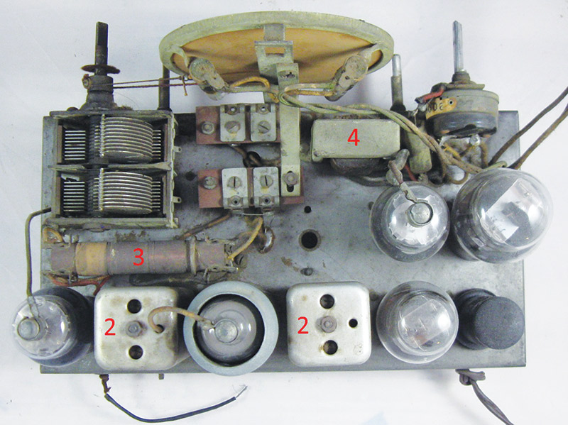
OK, in this part circuit I used to work on, shows a receiver circuit operating in the VHF band.
there's a selection of 2, 3, 4 and 5 pin variable inductors. The 5 pin inductor is in the middle of the
circuit, labelled T2, just before the Mixer FET

Comm2000 RX-TX Brd.jpg
 
Thanks Dave.
I didn’t know that. I also thought the OP was talking about a ‘canned’ variable capacitor.
Us MUCH younger guys have no chance with our elders experience:)

Martin
 

davenn

Moderator
Thanks Dave.
I didn’t know that. I also thought the OP was talking about a ‘canned’ variable capacitor.
Us MUCH younger guys have no chance with our elders experience:)

Martin

:) :)

in old tube radios variable inductors were much larger ...
see the two, labelled 2, between the tubes

NV_0515_Koebel_Figure15B.jpg


I cant find a photo of the insides of one of those type

but here's a photo of another old one, They would have an iron or ferrite core on a screw

inductor1.jpg
 

davenn

Moderator
I still feel the OP was talking about a can. But let’s wait for a response.

Martin


not sure what your definition of a "can" ?

but the "cans" I have shown are what we would typically be referring to

Ohh I have heard of the really old electrolytic caps referred to as cans

c-ec40-20-20-nos.png


on the other hand ... old radio operators would refer to headphones as "cans"
 
what are the 5 pins in a variable inductor used for
There's also variable inductors ... has been since the beginning of radio ;) ;)
here's a newer version

OIP.Sm0oEcrHu2d2qEr9EbCRVAHaHa

I took it to be these immediately.
They often form part of resonnant circuits in the radio, to allow selection of bands, to filter out things that are not in the intended band.
As you can see form the ciruit posted above, there's a bit involved to use them well.
You can use them to make simple RF oscillators.
Maybe google oscillators. and look into some of the different forms.
 

bertus

Moderator
ohhh Bertus .....

There's also variable inductors ... has been since the beginning of radio ;) ;)
here's a newer version

OIP.Sm0oEcrHu2d2qEr9EbCRVAHaHa


@Poloko ... please note tho. just because there are 5 (6) pins on the bottom, not all of them may be connected to a coil. 5 or 6 pin (2 or 3 either side) is just the standard former type.
The circuit designer will use what he/she needs what they need for the type of inductor they are designing .... see my next post with the schematic showing multiple variations in the number of pins used

@davenn , I know those. They are used as tuned circuits for the oscillator, IF (Intermediate Frequency) and detector circuits.
TOKO and MURATA are well known brands for them.
TOKO_if_coils.png
An example of the connections:
TOKO_if_coils_connections.png

In an AM radio you can possibly find these coils:
7mm can transformers.jpg

Here is an other page with info:
http://www.rfcandy.biz/communication/ifcan.html

Bertus
 
Top