Maker Pro
Maker Pro

Radio Control RF 433

I'm trying to sort out a remote ON/OFF button for a LED. My solution was to buy a remote+receiver to complete this function.

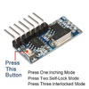
I bought - VIPMOON® 14 Key RF Remote Controller, DC 5-24V Mini Wireless RF Remote Dream Color Controller for SMD 5050 2835 WS2811 WS2812B RGB LED Strip Lights(pic.1)

- Ahevo G4 2835 SMD LED 350LM Light Crystal Bulb Lamps 4 Watt AC/DC 12V

- 9V Battery

I have removed the connectors of the receiver. I have RED and BLACK at Supply(Battery) and RED, WHITE, GREEN for Receiver.

So i connect - RED(Battery) with RED(Receiver) and Black(Battery) with Black(Receiver). SUPPLY

- WHITE(LED) with GREEN(Receiver) and BLACK(LED) with RED(Receiver) LED-RECEIVER(pic.2)

Light is on at half intensity. ON/OFF button makes the light to change modes i belive because the light starts blinking in different mods after each press. Other butons makes it blink(like is receiving signal but dosen't do what it sopposed to do). If i join WHITE(Receiver) with GREEN(Receiver) and WHITE(LED) the light intensity goes up and the buttons same things. I can't manage to turn it ON/OFF.

When i connect - RED(Battery) with RED(Receiver) and Black(Battery) with Black(Receiver). SUPPLY

- WHITE(LED) with WHITE(Receiver) and RED(Receiver) with Black(LED). LED-RECEIVER

Light is at high intensity. Whatever i press id dosen't do a thing. If i connect GREEN(Receiver) to RED or WHITE remains at the same intensiry and no response from buttons.

On the back of the Receiver RED is + ; WHITE between G G - ; GREEN D

Can anyone tell me what i'm doing wrong? I just want to turn ON/OF the circuit.

Or can someone point me in the right direction to achive this simple function.(Like buying the boards-transmiter-receiver).

Thank you!
 

Attachments

  • 1.jpg
    1.jpg
    34.2 KB · Views: 2
  • rsz_2.jpg
    rsz_2.jpg
    109.2 KB · Views: 3
Best if you supply the details/specs you have there or a link to the product, otherwise it's like trying to follow McGyver logic.

Add to this, whenever I see 9v battery mentioned, my suspicions are a smoke alarm type battery which , for many applications , has insufficient oomph to drive the required circuitry.
 

Harald Kapp

Moderator
Moderator
This controller is not suitable to your project. It is meant to control strips of addressable LEDs. These have constant 5 V power supply and a data line that controls brightness and hue via a serial protocol.

You're looking for something like this remote controlled switch, I guess.
 
I'm looking to achieve just ON/OFF function. That's why i was just tried to make it work on just that not for the rest of the functions. Anyway i have abandon that one and bought this new 4 channel receiver transmitter: https://www.aliexpress.com/item/400...earchweb0_0,searchweb201602_,searchweb201603_

So i have tried to follow the scheme and make connection like in the pictures.
When i press the button it make the LED from the transmitter board to turn ON/OFF.
What i'm doing wrong?
Thank you all for the answers and suggestions, much appreciated!
 

Attachments

  • rsz_img_20201002_081456.jpg
    rsz_img_20201002_081456.jpg
    85 KB · Views: 1
  • rsz_img_20201002_081424.jpg
    rsz_img_20201002_081424.jpg
    87.5 KB · Views: 1
  • rsz_img_20201002_083957.jpg
    rsz_img_20201002_083957.jpg
    90.2 KB · Views: 1

Harald Kapp

Moderator
Moderator
Your photos are not very crisp and too far away to identify your circuit.Also wires going off-photo could go anywhere.

Help us to help you:
Make close-ups that allow clearly to see which wire goes where. Use different colors for the wires. Usually Vcc (+Vbat) is red, GND (-Vbat) is black (or blue), use green, orange, violett, white etc. for the different signals so they can be clearly identified. Put a description which color is which signal in your text. Describe the kind of switches you use. A good schematic diagram of your setup will also help (doesn't have to be computer generated, a manual sketch properly scanned will do)

From what little I can recognize it looks as if you use a momentary switch to power the transceiver with the input contact K4 being permanently connected to ground. I'm not sure if that will work at all. It surely isn't imntended to be used this way. The diagram on the webpage shows power (Vcc, GND) being permanently connected to the transmitter. The action is then triggered by pressing a momentary switch connected to one of the inputs K1...K4.

Also: If the coil on top of your 2nd photo is the antenna, make sure it doesn't create a short circuit to the underlying components or between the windings as the wire of the coil seems not to be insulated.
 
Thank you for your time and answers! Obviously I'm new to this electronic and is quite hard for me to understand the schematic of the product. In the pic.3 i did the diagram as you say after tried to unlock the schematic from the product description. As you say is wrong and i get it but i'm not sure what to connect to make it work. My phone camera is crap too and that's why the pictures are like this(sorry!), that's why i have attached the schematic diagram. No other different colours for wiring at the moment.
Here are some better pictures of what i did. 1x 2A Press Switch.
2x 1.5 AAA Batterie for Transmitter
1x 9v Battery for Receiver
1x G4 2835 SMD LED 350LM Light Crystal Bulb Lamps 4 Watt AC/DC 12V
Transmitter : Battery / (+)Positive - (+)Positive / Transmitter ;
Battery / (-)Negative - (-)Negtive / Transmitter ;
Battery / (-)Negative - Button - K1 / Transmitter;
Receiver : Battery / (+)Positive - (+)Positive / Receiver ;
Battery / (-)Negative - K1 / Receiver ;
K1 / Receiver - LED - VT / Receiver ;
How a good connection would look for this scheme?
Thank you so much!
.rsz_20201002_112655.jpg rsz_20201002_112617.jpg rsz_20201002_112539.jpgrsz_trsrcs.jpg
 

bertus

Moderator
Hello,

Are you trying to power the led direct from the receiver pin?
You could try via the ULN like the other pins.
That will not work as the pin can not deliver the needed current.
Also the ledlamp will not work very long on the tiny 9 volts bettery.

Bertus
 
Hi! Thank you for the answer.
Can you please show me on the schematic diagram how i should wire the boards with the available components in order to make it work. I need to have 1 channel with ON/OFF function.
I got :
-1x 2A Press Switch.
-2x 1.5 AAA Batterie for Transmitter
-1x 9v Battery for Receiver
-1x G4 2835 SMD LED 350LM Light Crystal Bulb Lamps 4 Watt AC/DC 12V

Much appreciated! Thanks!
 
This is what i'm trying to understand but i don't. So please explain me like for a stupid guy ..
Clear RED and fill it in the correct order of wiring..
This is my example : Legend : [BTN]= Button/Switch ; [LED]= LED bulb
Transmitter: Battery:
[1T]Negative - [2B] [1B]Positive - [2T]
[2T]Positive - [1B] [2B]Negative - [1T]
[3T]K1- [BTN] - [1T]
[4T]K2-
[5T]K3-
[6T]K4-
[7T]ANT-
Receiver: Battery:
[1R]GND - [1B]Positive - [2R]
[2R]Positive - [1B] [2B]Negative - [3R]
[3R]D0 - [2B]
[4R]D1 -
[5R]D2 -
[6R]D3 -
[7R]VT - [LED] - [3R]

Hope i made it clear.
Thank you!
 

Harald Kapp

Moderator
Moderator
That will not work as the pin can not deliver the needed current.
The schematic shown on the website linked in post #5 shows LEDs with series resistor directly connected to the receiver. But this means a single LED with maybe 5 mA to 10 mA current consumption.

The LED as shown in @bertus ' diagram will immediately burn through if it were a single LED. You need a series resistor to limit current, see here.
@Nowatiny : Your image shows a LED lamp (not a singleLED) which will have internal current limiting but will definitely draw more than 5 mA - 10 mA, more than the receiver can deliver. SO using an ULN or a simple transistor switch is required.

Transmitter: Battery:
[1T]Negative - [2B] [1B]Positive - [2T]
[2T]Positive - [1B] [2B]Negative - [1T]
[3T]K1- [BTN] - [1T]
[4T]K2-
[5T]K3-
[6T]K4-
[7T]ANT-
o.k.
Receiver: Battery:
[1R]GND - [1B]Positive - [2R]
[2R]Positive - [1B] [2B]Negative - [3R]
[3R]D0 - [2B]
[4R]D1 -
[5R]D2 -
[6R]D3 -
[7R]VT - [LED] - [3R]
not o.k.
Firstly, you inverted the pin numbering (see image below). But I hope this is only a mismatch in your table as your image in post #7 seems to be correct.
Assuming you will use your LED lamp, you'll need some sort of driver (ULN or transistor, see above). Bertus has shown how to connect this. Or use (for test purposes) a single LED with series resistor directly connected from D0 to Ground (battery -) a shown here (from the website of the vendor):
upload_2020-10-2_17-16-12.png

Or using Bertus' image freed from the unnecessary ballast:
upload_2020-10-2_17-24-35.png
 

bertus

Moderator
Hello,

@Harald Kapp , He is using a ledlamp in stead if a regular led.
It is supposed to work on 12 Volts AC/DC.
As it is 4 Watts, it will likely take about 300 mA.

Bertus
 
Still hard to understand. So for receiver I'll connect
Battery Positive - Positive Receiver
Battery Negative - LED - D0
?
I'm sorry but i'm so confused!
Thank you for your patience!
 

bertus

Moderator
Hello,

Looking at this picture from the given website:

nowat_receiver.png

I see an 12F625 PIC chip, likely used as the decoder.
That chip can drive 30 mA max on its pins.
Your led requires about 300 mA, so you will need an amplifier for the current, like the ULN2003.

Bertus
 
Hello,
Looking at this picture from the given website:
I see an 12F625 PIC chip, likely used as the decoder.
That chip can drive 30 mA max on its pins.
Your led requires about 300 mA, so you will need an amplifier for the current, like the ULN2003.
Bertus
This mean that i need another board in order to make it work? I ve through some comments that someone was saying similar thing but at the end has correct himself saying that it works without needing any other components.
What is unclear to me is if i made the right wiring?!

I have this now:
Transmitter :
Battery Positive - Positive Transmitter
Battery Negative - Switch - K1
- Transmitter Negative
Receiver:
Battery Positive - Positive Receiver
Battery Negative - LED - D0

...and i have light at my LED Bulb at low intensity. When i press the Switch it makes the LED to blink.
Trying to 1. Delete existing data: Press learning button(on the receiver) 8 times. Response: LED flashes 7 times. ..and i don t get the response.
 

bertus

Moderator
Hello,

The other receiver is capable of switching 2 Amps.
(the third option on the page : reciever only).
It has two power leads and two load leads.

Bertus
 
Hello,
The other receiver is capable of switching 2 Amps.
(the third option on the page : reciever only).
It has two power leads and two load leads.
Bertus
Transmitter module
Transmitting power: 11dbm
Emission current: 10 mA
Rate of fire: maximum 10KB / S
Operating Voltage: DC 3V-24V
Encoding : 1527 Learning code
Each module has a unique ID address code.
All modules K1-K4 four key code is the same.

Receiver module
Working Voltage : DC3.3~5V
Quiescent Current : ≤5mA
Output current : 10 mA
Working Frequency: 433MHz
Receive Sensitivity: -108dB
Working Temperature : -25~75
Working mode: ①Momentary Mode;②Toggle Mode; ③Latched Mode.

It is? I'm not sure! You guys talk a different language.
Thanks for all answers and patience!

I have uploaded a video with the above wiring that made light.
What should i do next?


bertus

Moderator
Hello,

From the other receiver:
Receiver module :QA-R-011
Working Voltage: DC 3.6V~24V.
Maximum Load: 2A.
Static Current: 3.6 mA ~ 5.5mA.
Working Frequency: 433MHz.
Reception Sensitivity: ≥ -107dBm.
Modulation Mode:ASK (superheterodyne).
Number Of Stored Remote Controls: ≤ 10.
Working Mode: Momentary, Toggle, Latching Mode.
Learning Style: Learning Button.
Working Temperature: -20 degrees 80 degrees.
Appearance Size: 26mmx 13mm x 1mm (length × width × high).

Bertus
 
Top