Failed again:
Here are my steps
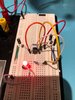
Prepared the 555 by shorting pins 2 and 6 and pins 4 and 8
Mounted it on breadboard
Connected Pin 4 to +
Connected + side of Capacitor to Pin 4 and the - side to ground
R1 connected to Pin3 and pin6
Connected other capacitors' + side to pin 3 and the - side to ground
Connected pin 8 to +
Connected Pin 1 to ground
Connected + side of LED to pin 3 and - side to ground
Here are my steps
Prepared the 555 by shorting pins 2 and 6 and pins 4 and 8
Mounted it on breadboard
Connected Pin 4 to +
Connected + side of Capacitor to Pin 4 and the - side to ground
R1 connected to Pin3 and pin6
Connected other capacitors' + side to pin 3 and the - side to ground
Connected pin 8 to +
Connected Pin 1 to ground
Connected + side of LED to pin 3 and - side to ground
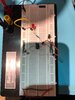
") ). For your next photo try better uniform lighting and higher zoom, so we can see the wiring and the orientation of components better. Maybe two or more photos with different zoom levels for overview and detail. We have a resource on how to make good shots of pcbs which may help with your breadboard setup, too.
). For your next photo try better uniform lighting and higher zoom, so we can see the wiring and the orientation of components better. Maybe two or more photos with different zoom levels for overview and detail. We have a resource on how to make good shots of pcbs which may help with your breadboard setup, too.