Maker Pro
Maker Pro

Questions regarding H-bridge

Hello,

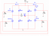
I have some question regarding H-bridge (MOSFETS). I have attached the circuit the I simulated and you can see it below. Anyway, from my understanding, when S1 is pressed, Q1 and Q4 will act as short line switch (in that case it will be saturated), making the current flow through them and therefore causing the motor to spin (I replaced the motor with the LED because I couldn't find a symbol for it in Multisim), while Q2 and Q3 will be working in the cutoff region. Am I getting this correct?

My second question is, why do we need to add a high value (1M ohms) resistor to each gate? Why not simply ground the gates without the resistors?

Question 3, how can I control the speed of the motor?

Thank you.
 

Attachments

  • H-Bridge Simulation.PNG
    H-Bridge Simulation.PNG
    23.2 KB · Views: 141
Last edited:
Yes. You get the idea.

The high value resistor ensures the transistor turns off by pulling down gate voltage when it's off instead of floating. If the gates were grounded, then they couldn't be turned on because it'd be a voltage to ground short.

The H-bridge is designed to simply change polarity, but if the gate signals were fed with a pwm circuit it would control the motor speed by briefly turning it on and off.
Edit: That is, quickly turning it on/off with pulses.
Perfect answer. I had the same thought about the high value resistor, but I wasn't entirely sure. Thank you.
 

Harald Kapp

Moderator
Moderator
There's one issue: the IRF540 is an N-MOSFET with a threshold voltage Vgsth between 2 V and 4 V. Using this in the high leg of the bridge (Q1, Q3) results in a loss of voltage and consequentially power to the load.
I recommend you use P-MOSFETs instead (e.g. IRF9540), source and drain swapped (compared to IRF540). You will also need an inverted drive for the P-MOSFET.

Diodes D1...D4 are not required, they have no efefct in this circuit. To add protection from the motor's flyback voltage use e.g. zener diodes as shown near the bottom of this page.
 
To add protection from the motor's flyback voltage use e.g. zener diodes as shown near the bottom of this page.
Or, delete D1-D4 and use the zener diodes already built into the four MOSFETS as shown on the OP schematic.

Also, the schematic is missing two connection dots where the diodes join the "motor". To make sure crossed lines are not misinterpreted, don't have any. If D1 and D3 are staggered sideways, they join the motor signal as two T connections instead of one X connection. Even without a connection dot, the T is not ambiguous.

ak
 
Do you understand that Q1 and Q3 will only barely turn on conducting a very low current? They are "followers" not switches. If you want them to switch on well then their gate must be 10V higher than the power supply voltage. Usually P-channel Mosfets are used on the high sides of an H-bridge.
 
There's one issue: the IRF540 is an N-MOSFET with a threshold voltage Vgsth between 2 V and 4 V. Using this in the high leg of the bridge (Q1, Q3) results in a loss of voltage and consequentially power to the load.
I recommend you use P-MOSFETs instead (e.g. IRF9540), source and drain swapped (compared to IRF540). You will also need an inverted drive for the P-MOSFET.

Diodes D1...D4 are not required, they have no efefct in this circuit. To add protection from the motor's flyback voltage use e.g. zener diodes as shown near the bottom of this page.
Now I am confused, why Zener diodes and not unidirectional (forget the term) diodes?
 
Diodes are unidirectional (sort of).
They conduct one way when forward biased and break down when reversed biased, allow current to flow in the opposite direction.
Zeners are designed to do this. The technical term is avalanche I think or zener affect.
A normal diode, say 1N4007, has a high breakdown voltage. So reverse biasing, it will breakdown at <> 90 Volts. Forward biasing, it will conduct around 0.6-0.7V.
Quantum mechanics is certainly not my thing, nor are the technical terms involved.
This thread is also nearly 4 yrs old.

Martin
 
Last edited:

Harald Kapp

Moderator
Moderator
Now I am confused, why Zener diodes and not unidirectional (forget the term) diodes?
That should have been Schottky diodes, my fault.
@Obit
Anyway this thread is almost 4 years old and the op never came back in the years following. If you want to discuss this issue further, please create new thread of your own.
 
Top