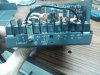
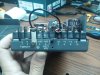
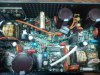
as you may see in the picture on each smps the lead used as "negative" is connected to the chasis.
No it isn't. In one image, +S and +V (bridged) are connected to the chassis, meaning this power supply produces negative voltage on -S and -V (bridged) with respect to the chassis. In another image, -S and -V (bridged) are connected to the chassis, meaning that power supply produces positive voltage on +S and +V (bridged) with respect to the chassis.
The bridge conductor installed between +S and +V and between -S and -V is used in lieu of a separate pair of sense wires (usually small gauge) installed between the power supply output sense terminals, +S and -S, and the load terminals to provide voltage regulation at the load. With those two jumpers in place, voltage regulation occurs only at the output supply terminals, +V and -V. The load conductors connecting to +V and -V may be considerably larger than the pair of sense wires to reduce the voltage drop in the load conductors, but without a separate pair of sense wires a voltage drop will occur between the power supply output on +V and -V and the load connected to those two terminals. This may or may not be important, depending on circuit design, load current, and other factors.
Many power supplies have internal resistors of about 100 ohms permanently wired between the output terminals and the corresponding sense terminals. This allows the power supply to operate more or less normally if someone happens to remove the bridge jumpers, but still allows normal remote sensing if sense wires are used.
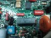
The outputs of SMPS units are isolated from mains power, so there is no reason not to use one as a positive output supply and the other as a negative output supply with respect to chassis common, as shown in your excellently photographed images..
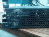
I would attempt to repair the Lamda power supplies before replacing them with cheap Asian imports of unknown design quality. Back in the day, Lambda power supplies were virtually bullet-proof, but it seems like today everything is disposable rather than repairable. <sigh>