Maker Pro
Maker Pro

Question about Thévenin's theorem assignment

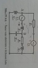
In this task I'm supposed to determine the value of current between points A and B (Iab). In order to do that I have to calculate the voltage between those 2 points. And in order to do that I have to calculate the value of current passing from point A to point B. But current I1 gets split in one point. So through capacitor C4 is passing current I2 instead of I1.

What my question is, how do I calculate the value of current I2? And did I correctly calculate the value of I1? And also did I define voltage Uab right?

The whole task is supposed to be done in complex numbers btw. Sorry if I misspelled something. Also I put a picture from the book if you can't see the values.
 

Attachments

  • 20180520_172042.jpg
    20180520_172042.jpg
    198.7 KB · Views: 98
  • Screenshot_20180520-172138.png
    Screenshot_20180520-172138.png
    336.4 KB · Views: 56
  • 20180520_172211.png
    20180520_172211.png
    92.6 KB · Views: 99
This is what I meant to write in the first picture.

I get the impression that you do not have any idea of how to perform loop or node analysis to find circuit voltages or currents. You must learn how to do that before you have any chance of solving that problem.

Ratch
 
I get the impression that you do not have any idea of how to perform loop or node analysis to find circuit voltages or currents. You must learn how to do that before you have any chance of solving that problem.

Ratch
Yeah that really helps me out a lot. Thanks.
 
On first seeing this circuit, my first inclination was to perform a nodal analysis in the complex frequency domain, because that is how I always analyze circuits. But realizing that this particular problem is in the steady-state frequency domain, it can be redrawn as simple resistors & batteries, equations derived to solve for the node voltages, then substitute into these equations the corresponding complex-valued impedance and voltage sources in place of the resistors & batteries.
Complex-Impedance-Loop.png

Here is the form of the original circuit redrawn as resistors & batteries. It may be less daunting to derive the equations in a simple resistor form rather than in complex impedance form (but use no numerical values until the final step.)
Complex-Impedance-Loop-2.png

Here is the resistor circuit slightly rearranged. It should be easy enough to get a Thevenin equivalent for U1, R1, & R3. Then all that remains is a simple loop to analyze.
 
Top