Hi,
I have a query regarding transistors in push/pull configuration for switching between +ve/-ve rails.
Referencing the example at the top of this page http://www.ecircuitcenter.com/Circuits/pushpull/pushpull.htm

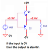
In my application, VS1 will be a 0 to 3V3 digital signal, which I want to convert to +/-5V (eg 0V becomes -5V, 3V3 becomes +5V).
I understand 3V3 to saturate the NPN b-e, resulting in output +5. However I'd need -0.7V instead of 0V input to saturate the PNP side because the output is referenced to 0V. Correct?
How would I go about resolving this? I thought I could perhaps add a potential divider to the output to replace the 0V with ~1.5V. I haven't seen any diagrams online that do this, so I would guess that's because it's a bad idea.
I'd prefer to use basic components if possible (no op-amp, comparator or ICs etc).
Can anyone point me in the right direction?
Thank you!
I have a query regarding transistors in push/pull configuration for switching between +ve/-ve rails.
Referencing the example at the top of this page http://www.ecircuitcenter.com/Circuits/pushpull/pushpull.htm
In my application, VS1 will be a 0 to 3V3 digital signal, which I want to convert to +/-5V (eg 0V becomes -5V, 3V3 becomes +5V).
I understand 3V3 to saturate the NPN b-e, resulting in output +5. However I'd need -0.7V instead of 0V input to saturate the PNP side because the output is referenced to 0V. Correct?
How would I go about resolving this? I thought I could perhaps add a potential divider to the output to replace the 0V with ~1.5V. I haven't seen any diagrams online that do this, so I would guess that's because it's a bad idea.
I'd prefer to use basic components if possible (no op-amp, comparator or ICs etc).
Can anyone point me in the right direction?
Thank you!