Hello guys!
I have a digital clamp meter (Benning CM 1-2, I have uploaded two photos of the pcb board) and it has two problems:
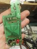
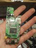
1. The Clamp meter's two cables are disconnected from the PCB board and I don't know where exactly to solder them. However I have seen two possible pins on the board (I marked them with a red circle) that might be the right place for the two wires
2. The device does not turn on. Even with new batteries, when I turn it on nothings happen in the screen.
I have uploaded two photos. Have you any idea?
Thank you very much in advance
I have a digital clamp meter (Benning CM 1-2, I have uploaded two photos of the pcb board) and it has two problems:
1. The Clamp meter's two cables are disconnected from the PCB board and I don't know where exactly to solder them. However I have seen two possible pins on the board (I marked them with a red circle) that might be the right place for the two wires
2. The device does not turn on. Even with new batteries, when I turn it on nothings happen in the screen.
I have uploaded two photos. Have you any idea?
Thank you very much in advance