Maker Pro
Maker Pro

Power supply Current limiting , using what value resistor? Mercury Relays are dirty

Power supply Current limiting , using what value resistor?

The power supply I have has current limiting knobs but it doesn't show you how much current it is outputting until you hook it up to the circuit

I want to know BEFORE i hook it up to the circuit how much current is outputting out of the external power supply

For some reason the external powers supplies don't tell you how much current is outputting unless its hooked up to a circuit


What value resistor and how many watts do I need?

A circuit board I'm working on has Mercury Relays that are dirty with corrosion, What can I use to clean the mercury contacts on the relays? they are from the 60's these relays
 
Last edited by a moderator:
Harald Kapp

Moderator
Moderator
For some reason the external powers supplies don't tell you how much current is outputting unless its hooked up to a circuit
That is because they don't output current unless connected to a circuit. Set the current limit by short-circuiting the power supply, setting the current, then removing the short circuit. Now connect the power supply to your circuit and the current will be limited to the preset value.

What value resistor and how many watts do I need?
What for do you need it? Current limiting doesn't work by just inserting a resistor in the circuit. A simple resistor will limikt current but it will also reduce the output voltage depending on the current due to the voltage dropp across the resistor. Not a good idea. Read this article on current limiting. The circuits shown there provide constant output voltage as long as the current limit is not reached. They will limit current for higher loads. In the overload case the power is lost in the transistor, not so much in the sense resistor.

Wattage is P=i²*R, alternatively P=V²/R, so knowing either I or V and R you can calculate the power required.

I don't think you will be able to clean the mercury wetted contacts. Relays wit mercury wetted contacts are sealed (the mercury is meant to provide good conductivity at low currents, but is poisonous to man).
You can try a kind of "electrical cleaning" by sending a high current through the contacts.
 
I think what he means Harald is that some power supplies allow you to set the current limit before hand. The Thurlby Thandar ones I use do allow you to do this before you switch on, but some of the cheaper ones don't.
Adam
 
I think what he means Harald is that some power supplies allow you to set the current limit before hand. The Thurlby Thandar ones I use do allow you to do this before you switch on, but some of the cheaper ones don't.
Adam

Yes this is true,

I'm guessing the cheaper ones don't have a current sensor circuit ? or what is it missing?

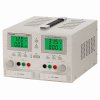
It's a Tenma 72-6610 power supply

If I short circuit the Positive to the Negative terminals on the power supply together , I can set the current limit , but it gets very HOT , is this bad to do to the Tenma power supply? how else can I adjust the current limit before I hook it up to the circuit board?
 

davenn

Moderator
If I short circuit the Positive to the Negative terminals on the power supply together , I can set the current limit , but it gets very HOT , is this bad to do to the Tenma power supply?

yes, that's bad for any PSU

how else can I adjust the current limit before I hook it up to the circuit board?

you could use a resistor value that approximates the resistive value of your load

even my moderately expensive twin variable PSU with current limiting doesnt allow me to set a specific current first

If Im unsure of what the circuit will require, I will ALWAYS start the power supply with the current set to minimum and then very slowly turn up the current and observe on the Ammeter what the value is

attachment.php


Dave
 

Attachments

  • MP3087.jpg
    MP3087.jpg
    20.8 KB · Views: 359
Last edited:
Yes this is true,

I'm guessing the cheaper ones don't have a current sensor circuit ? or what is it missing?

It's a Tenma 72-6610 power supply

If I short circuit the Positive to the Negative terminals on the power supply together , I can set the current limit , but it gets very HOT , is this bad to do to the Tenma power supply? how else can I adjust the current limit before I hook it up to the circuit board?

Set to 12V use car headlight:

Google said:
The average halogen lamp uses about 55 watts of energy, with a xenon lamp using 35 watts

the halogen would pull about 4.583Amps and the xenon about 2.917A

seeing how your power supply can only handle 3A should be fine.

Avoid short circuit at 0 ohm you have an infinite amperage - but only a supper conductor could pull off a true 0 ohm.

Note what I stated above is only true if the Amp limit will remain constant as you change the voltage
 

(*steve*)

¡sǝpodᴉʇuɐ ǝɥʇ ɹɐǝɥd
Moderator
even my moderately expensive twin variable PSU with current limiting doesnt allow me to set a specific current first

My extremely cheap one does :)

Note that this is the one that Dave Jones destroyed, and was subsequently supplied with an upgrade which is far more reliable (and mine is an upgraded one).

PS-3005D.jpg


I often have the current limit set as low as 20mA. The only issue with these is that they have an output capacitor which can deliver a current pulse if you turn on the output before connecting the load.

But yeah, if you can't set it before applying a load, and if the supply doesn't like a short, connect a load that will give you the current you want (vary the voltage if required to get the exact current) then wind back your current limit until it *just* trips.

Remember to reset the voltage to the correct value, and also remember to use a resistor that can handle the power
 
you could use a resistor value that approximates the resistive value of your load

How can you find out the LOAD of the circuit?

Use an Ohm meter and measure the power supply inputs to the circuit?

even my moderately expensive twin variable PSU with current limiting doesnt allow me to set a specific current first

The PSU that can set the current limit BEFORE , are called what? and what is inside the PSU that allows you to do this? is it a current sensing circuit?

If Im unsure of what the circuit will require, I will ALWAYS start the power supply with the current set to minimum and then very slowly turn up the current and observe on the Ammeter what the value is

Yes but how can I find out what the current is set to before I hook it up to the circuit? what kind of circuit would I need , it is a current sensor circuit or a shunt circuit like what's in a current meter?

Can I put my DVM meter in currrent mode across the PSU terminals to set the PSU current limit?
 

(*steve*)

¡sǝpodᴉʇuɐ ǝɥʇ ɹɐǝɥd
Moderator
Avoid short circuit at 0 ohm you have an infinite amperage - but only a supper conductor could pull off a true 0 ohm.

Note what I stated above is only true if the Amp limit will remain constant as you change the voltage

That's not necessarily true.

In fact for a bench power supply it should not be true.
 

(*steve*)

¡sǝpodᴉʇuɐ ǝɥʇ ɹɐǝɥd
Moderator
How can you find out the LOAD of the circuit?

I expect you're asking "How can I find the expected current required for the circuit?"

That's something you need to know (or measure)

Use an Ohm meter and measure the power supply inputs to the circuit?

For very simple circuits this will work, but probably not for anything more than a circuit comprising more than resistors.

Yes but how can I find out what the current is set to before I hook it up to the circuit? what kind of circuit would I need , it is a current sensor circuit or a shunt circuit like what's in a current meter?

You estimate. If it's 5W and runs from 12V, then the current will be under half an amp.

Can I put my DVM meter in currrent mode across the PSU terminals to set the PSU current limit?

You can, but the cavets about your power supply heating up apply. Also be VERY careful you select the correct range on your meter.

If you wanted to set the limit for 1A, you could, for example, connect a 5 ohm 10W resistor across the power supply, set the voltage for 5V and then adjust the current limit until it is close to tripping. The load is 1A, thus your limit is set slightly above that.

Of course a lot depends on how your power supply indicates that it's limiting current (mine has a LED which illuminates). It's also possible that you see nothing other than the output voltage decreasing.
 
@ (*steve*)
How does the current limit work with your unit. In other words, how does it enable you to set it before a load is connected.
 

(*steve*)

¡sǝpodᴉʇuɐ ǝɥʇ ɹɐǝɥd
Moderator
@ (*steve*)
How does the current limit work with your unit. In other words, how does it enable you to set it before a load is connected.

There is a voltage/current button. You press that once to set the voltage, and again to set the current.

When you've pressed the button the display changes from the actual current or voltage to the set current or voltage and one digit flashes. Rotating the knob changes that digit.

There is another pair of buttons marked < and > that allow you to control another digit. If you're really keen, you can change the current limit from 0.001A (1 mA) up to 5A just using the least significant digit, but you don't often want to do that :))

If you stop doing stuff for about 3 seconds the display stops flashing and reverts to the actual output voltage and current (it's not exactly that, because you can turn the output completely off too, and in that state it displays the set voltage and current).

There are some similar units which have a pair of knobs for voltage and current. One does a coarse adjustment, the other a fine adjustment. (here is an example). I'm not sure if they show the set value of current as you're adjusting them.
 
@ (*steve*)
Thanks for the replay. My question was not very clear. What I really want to know is how is the
current limit achieved electronically.
 

(*steve*)

¡sǝpodᴉʇuɐ ǝɥʇ ɹɐǝɥd
Moderator
I don't know. I have not examined the unit in that much detail I don't have a schematic.
 
To set the Current limit on a power supply, you directly short out the positive terminal to the ground on the power supply. that is what my manuals say to do, but is this ok to do? you set the current limiter by shorting out directly

Why doesn't this damage the power supply? what is protecting it from getting damaged?

What circuit use current limiting? as an input or injecting it

Current limiting circuit example:
By Driving current to an op amp or a current comparator to switch the output state , you have to set the current limit
 

(*steve*)

¡sǝpodᴉʇuɐ ǝɥʇ ɹɐǝɥd
Moderator
To set the Current limit on a power supply, you directly short out the positive terminal to the ground on the power supply. that is what my manuals say to do, but is this ok to do? you set the current limiter by shorting out directly

If that is what the manual for the power supply says to do, then that's what you should do.

Why doesn't this damage the power supply?

The spirit of the engineer who designed it.

what is protecting it from getting damaged?

The current limit (and the calculations of the engineer who designed it).

What circuit use current limiting?

Any circuit that needs to have a fixed or maximum current where the load may demand a higher current. e.g. a bench power supply, or a LED driver.

as an input or injecting it

I don't understand what you mean here.

Current limiting circuit example:
By Driving current to an op amp or a current comparator to switch the output state , you have to set the current limit[/QUOTE]
 
here is the schematic

When measuring from +13 red meter probe and the black meter probe is -13 volts , it creates a SHORT

Is it because the circuit boards power supply earth or chassis ground is different then the DVM meters earth or chassis ground?

Is this a ground loop problem?
 

Attachments

  • IMG_20140213_063923_648.jpg
    IMG_20140213_063923_648.jpg
    107.3 KB · Views: 145

(*steve*)

¡sǝpodᴉʇuɐ ǝɥʇ ɹɐǝɥd
Moderator
If you're measuring current across here then that's your first problem because that power supply (at least at that point) doesn't seem to have any current limiting.
 
What would make it have current limiting?

Protection Diodes would be in series? are protection didoes zeners?

Why is it ok to short circuit an external power supply unit to set the current limit, why doesn't the power supply get damaged?
 

(*steve*)

¡sǝpodᴉʇuɐ ǝɥʇ ɹɐǝɥd
Moderator
What would make it have current limiting?

Protection Diodes would be in series? are protection didoes zeners?

Why is it ok to short circuit an external power supply unit to set the current limit, why doesn't the power supply get damaged?

Let me give you an analogy.

Bad Analogy Guy said:
What makes a car suitable for running into other cars?

Two coats of protective blue paint? Are protective paints shiny?

Why is it OK to crash bumper cars together? Why don't the bumper cars get damaged?

So the answers are:

1) you need to have a suitable design to give a power supply current limiting or to make a bumper car.

2) Neither blue paint not diodes are protective even 2 coats (or 2 in series).

3) Shiny blue paint is no better than blue paint (and zener diodes not better than any other sort of diode) in this application.

4) bumper cars are made to tolerate crashing into each other. Some power supplies are made to tolerate short circuits. Neither get damaged because they are designed not to.

A bumper-car will have rubber bumpers all around and have a heavy construction, be limited to a low speed, and designed to withstand the loads involved in collisions.

A current limited power supply will have a circuit that (for example) reduces the voltage in the event of overload in order to keep the power dissipation within short or long term limits. It may do other things to limit dissipation (like it might shut down).

Painting a car blue will not make it a bumper car, and adding diodes will not make a power supply current limited.
 
Top