Maker Pro
Maker Pro

PLASMA CUTTER IGNITOR CIRCUIT

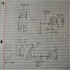
The following photos are of a section of circuitry that I am guessing drives or times a flyback transformer which goes to a spark gap and induces the arc of a hand held plasma cutter. The schematic is my best guess of circuitry. Any chance I can drive the IRFP264 MOSFET with bipolar transistors? Look familiar to anyone? Plasma cutter is a Lotos model LTP5000D. I have been unable to find a technical manual for this unit.POWER MOSFET 2.1.jpg POWER MOSFET SCHEMATIC GUESS 2.1.jpg
 
Yes you can drive your MOSFET with bipolar transistors, I do it all the time. But.. you have to consider the input capacitance of the chosen device and the expected driver rise time as this directly affect the current driven into the gate. Also, you would need some sort of clamp on the gate to limit any voltages reflected back from your transformer circuit through the MOSFET back to the gate circuit.
I use a simple totem pole bjt circuit to alternately charge and discharge the gate circuit.
 
CIRCUIT 1 1.1.png
Yes you can drive your MOSFET with bipolar transistors, I do it all the time. But.. you have to consider the input capacitance of the chosen device and the expected driver rise time as this directly affect the current driven into the gate. Also, you would need some sort of clamp on the gate to limit any voltages reflected back from your transformer circuit through the MOSFET back to the gate circuit.
I use a simple totem pole bjt circuit to alternately charge and discharge the gate circuit.
It has been a while since I have heard the term totem pole. Will you refresh my memory on that and give a nutshell tutorial on a totem pole bjt circuit if it is practical and you are willing ? I may readily recognize it or maybe not. Ran into a similar situation a while back with a "bubba" oscillator circuit. It appears that the totem pole circuit is what I general call a push-pull circuit. The circuit I posted is what I believe existed prior to burning up. I will be driving an N-channel enhancement mode MOSFET instead of a SiC JFET. I haven't done any calcs on Rg. I think Cgd and Cgs are accomplished with a 1.5KE250CA bidirectional diode.
 
Last edited:
It has been a while since I have heard the term totem pole. Will you refresh my memory on that and give a nutshell tutorial on a totem pole bjt circuit if it is practical and you are willing ? I may readily recognize it or maybe not. Ran into a similar situation a while back with a "bubba" oscillator circuit.
CLAMP DIODE 1.1.png I believe this was mnfctrs clamp circuit device.
 
See attached BJT Totem Pole schematic.
What would be the high end frequency before distortion? I'm guessing that the absence of an input resistor to the MOSFET gate relies upon the theory that the FET gate circuit passes no current. Close?
 
For the most part I don't use a gate resistor as it can restrict the rise time. Just get the totem pole as close to the gate as you physically can.
Because the gate source junction is quite capacitive, the input current to the gate is determined by the signal rise time and can be quite high.
The sum is: I= C*dv/dt. (That's from memory, hope I got it right)
Where C is in Farads
dv is the amplitude of the voltage transition.
dt is rise time in seconds.

The high end frequency will depend on the current gain vs frequency of the BJT's. and will be defined as its transition frequency. That can be determined from their data sheet. You will also need to consider their turn on and turn off times plus the time it takes for the device to respond to the signal as this will directly affect the maximum frequency you can expect.
With the exception of current gain, the same is also true for the FET.
Also bear in mind that if you are looking for a square wave output and you try to run at max possible F' then the signal will look more like a triangle. All these factors will also affect power dissipation in the output device.
 
Top