Hello to all,
I would like to ask for help.
I am making a student project which includes a parallel port.
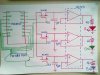
I am controlling the intensity of an RGB diode with D/A converter and connected on Intel 386DX through a parallel port. Its coded in Assembly language.
On the converter I need 5V power supply. I tried to give it from some control pin like Strobe, Initialize, AutoLineFeed, Select Printer, all of which are In/Out.
The problem is, when I send digital high to that pin (eg, Strobe), it gives 2,3V. Also when I send digital low- again 2,3V.
I was thinking maybe that is because it is not defined if it's In, or Out and it needs to be configurated like Out pin, but I couldn't find such code.
Any idea?
Thanks in advance
I would like to ask for help.
I am making a student project which includes a parallel port.
I am controlling the intensity of an RGB diode with D/A converter and connected on Intel 386DX through a parallel port. Its coded in Assembly language.
On the converter I need 5V power supply. I tried to give it from some control pin like Strobe, Initialize, AutoLineFeed, Select Printer, all of which are In/Out.
The problem is, when I send digital high to that pin (eg, Strobe), it gives 2,3V. Also when I send digital low- again 2,3V.
I was thinking maybe that is because it is not defined if it's In, or Out and it needs to be configurated like Out pin, but I couldn't find such code.
Any idea?
Thanks in advance