Sir spike1947
Thankee-thankee-thankee . . . for the feedsacks . . .DEE-lis-cous !
Now, how they define your relevant situation.
The presence of the
higher voltage supply equates with its being unloaded, if the A44 relay driver transistor was conducting and presenting the relay coil winding as loading, this meekly sourced supply votage would then pull on down closer to the coils voltage spec.
The
lower voltage supply presence and its value is telling us that its zener regulator diode was
not shorted and its voltage value is of such magnitude, as to initially feed the IR LED emitter and still be able to initially take the loss of R5 and pass voltage on down thru series elements D6 ( But NOT in your drawn backwards polarity manner, in which you had it installed ) and then thru R7 and into the base of The A44 to then drive it into conduction.
BUT lets backtrack, where you should be seeing the
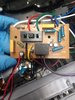
WHOLE circutry of a basic shredder being accomplished with only the top left corners content, with one exclusion, in one of your photos I see a Micro Switch being used, but not being in either of your schematics.
I expect it to be shown as installed in your power flow loop, such that it will close its contacts the instant that a shred item is being inserted in.
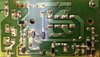
In my using your initial combinational pictorial drawing / schematic, that bottom left corner area didn't clarify too well . ..except . . only the "Paper full sensor" note.
That clued me in that they were not using a physical sampling of the fullness of the shredder collection bin in order to simply trip another Micro Switch.
Instead, the use of optical sensing detection, wherein a light path from LED to a physically spaced apart phototransistor is dependent upon that path being blocked as the shred bin reaches full capacity.
Thereby, I then knew what to sort out of that amalgam of cryptic component drawings, the newest drawing confirmed my initial query of " black rectangular IR " as its being a photodiode.
As well as the " Pale blue or White ??R50? " as being a LED.
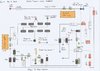
In consulting the complete new schematic . . . .
Initially make a step by step path from the units AC power input to the final AC ground by my drawn in BLUE arrow paths. Any open circuitpoint stops motor operation. * Take note that I placed your relays contact as now being
CLOSED with an unenergized coil or
OPEN upon the relays activation.*
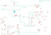
That then lets one see that the ZD1 derived low votage supply and its auxillary C1 filter capacitor initially feeds IR emitter diode and simultaneously directs a reduced supply voltage via R5 on down towards D6 ( its not installed
"sdrawkcab" anymore !) to pass on thru it and the final R7 path in order to then get into the base of A44.
BUT WHOAH !, back at that
NOW illuminated IR phototransistor, we find its now
LOW resistance is gobbling up all of that drive voltage and sending it direct to ground.
UNLESS the electromechanical manner in which they have chose to detect a full shred bin, then blocks the light path, such that the now changed into
VERY HIGH resistance of the photodetector lets the base drive for the A44 pass on down the path. ( Excepting a bit of time delay / hang time introduced by C2 downroute .)
Then, finally, with base drive present at A44, it closes power relay
K1 via its collector and
OPENS its
NORMALLY CLOSED relay contacts to disrupt the shredder motors power loop and shut down shredding operations until the shred bin is emptied.
And what I
REEEEELY think now . . . .if those electronics aspects check out . . . is that you probably are going to find my notations of having worn down loosey-goosey- wobbledey -obbledey motor brushes as being your units problem.
Thaaaaaassssssit . . . . .
Schematic Re Draw . . . . .
https://i.ibb.co/Ws9dz47/Shredder-Schematic-Re-Draw.png
73's de Edd . . . . .
The brain is a wonderful organ; it starts working the very moment you get up in the morning and doesn't stop until you get to work.
.