Maker Pro
Maker Pro

Organ power supply repair

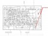
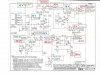
While trying to revive a component section of a 1979 Pro 222 Baldwin electronic organ, I cleaned connectors and pins on 5 of 23 daughter boards using contact cleaner.(This was successful frequently in the past) Prior to that, the remaining sections of the organ operated normally. After reassembling the daughter boards to the motherboard the organ did not play at all. Inspection of the main power supply revealed 2 overheated resistors and an overheated transistor. A schematic, PC board, and photo of the power supply with the current measured voltages adjacent to the correct value is shown. Also shown are the overheated resistors and transistor. Hard to believe this failure happened just as I was cleaning the 5 boards. Can’t imagine how I could have caused a power supply failure. Can anyone suggest which power supply components have failed? Appreciate any help I can get.
Thanks,
Jim B
 

Attachments

  • Organ power supply PC.JPG
    Organ power supply PC.JPG
    101.7 KB · Views: 134
  • Organ power supply schem.JPG
    Organ power supply schem.JPG
    120.3 KB · Views: 162
  • DSC02596.JPG
    DSC02596.JPG
    337.2 KB · Views: 135
Sir Jimbert. . . . . . . .

Consult your resubmitted marked up schematic and see that this circa 1980 s unit is basically missing its +27 volt supply output.
A concurrent side effect is that this +27V supply also sends a voltage sample to other supplies to activate them, thereby the loss of /or / declined outputs on others, I have flagged all of those supply points with BLUE boxes and asterisks.

In a powered down condition, initially ohm out R1 and R2 ? to se if either of those power resistors are open.
Also unplug Q1 power transistor from its socket on the heat sink and use ohmmeter to test betweeen all connections for a dead short. If it is clean, then go to diode test mode and check between Base to Collector and Base to Emitter to confirm good junctions of ~600-700 millivolts.
While you have the Q1 unplugged, also go over to the +27 volt buss just to the right of the second 10 ohm power resistor and its C1 0.05 ufd decoupling capacitor and ohm that out to ground see if you might have a short.

Waiting until you catch up . . . . .

SCHEMATIC REFERENCING :

Organ_Power_Supply.jpg


73s de Edd
 
73's de EDD,
Thanks so much for your reply. I will follow your suggestions and let you know how it turns out.
Jim B
 
73's de EDD,
Thanks so much for your reply. I will follow your suggestions and let you know how it turns out.
Jim B
73's de Edd,
I have checked R2 & R1 and they both measure 10 ohms. The Q1 power resistor seems OK, the values measured are base to Collector=461 millivolts and base to emitter = 480 millivolts. Measured the resistance across C1 in place and it is 1 ohm. I wonder if the 27 volts is getting shorted downstream. I think I'll remove the 27V connector that feeds all the PC boards and see if that affects the readings. If so, I'll look for the problem down there.
Jim B
 

davenn

Moderator
I wonder if the 27 volts is getting shorted downstream

That is a very likely option

I think I'll remove the 27V connector that feeds all the PC boards and see if that affects the readings.

that's a good start
it will prove if it is off the PSU board or if it is one of the power rails on the PSU board that the 27V goes to that is the problem

edit: reviewing the schematic I didn't see anywhere that the 27V leaves the PSU board
maybe you have a schematic for other boards that shows 27V going into them ?
 
That is a very likely option


that's a good start
it will prove if it is off the PSU board or if it is one of the power rails on the PSU board that the 27V goes to that is the problem

edit: reviewing the schematic I didn't see anywhere that the 27V leaves the PSU board
maybe you have a schematic for other boards that shows 27V going into them ?
Davenn,
Thanks for your reply. I've checked downstream on boards using the 27V and found a board with a misaligned connector. The 27V had indeed shorted to ground. Fortunately, no apparent damage and I'm back where I started. Now on to another section to get the entire unit working. Thanks so much for everyone's help.
Jim B
 
Top