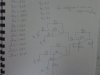
There's a problem with that question. Look at V3. It's connected to the summing node at the inverting input of the first op-amp. The non-inverting input is connected to 0V. If that op-amp was operating (pun intended) normally, the inverting input would also be at 0V. But the question specifies that V3 is +6V. If +6V is fed into that point, that will cause that op-amp's output to swing hard to positive, and the voltage won't be defined, because the power supply rails and the op-amp type aren't specified.
That would probably cause the second op-amp to do the same thing. So the circuit's output would be some undefined positive voltage somewhat less than the positive supply rail.
Perhaps that diagram is for a different question?

")