Maker Pro
Maker Pro

Onboard charger repair. Value of ZD?

Sir Bigrockk. . . . . . .

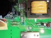
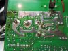
I certainly see no shielding need, considering its AC line input position on the board.
BUT. . . check it out and I believe that you will find that RF/EMI Cu foil shielded
rectangle actually is being an X capacitor that is connected directly across the AC
line input.
The floating Cu foil shielding is going to a GREEN /trace ground wire.


73's de Edd
 
Last edited by a moderator:
hi Bigrockk, I have the same problem in my battery charger too, but in the bank #2
How do you know which relay is damaged? why (-) negative reley? how do you found it?


When I was reviewing it, it caused a great short circuit and I burnt 2 resistors. Now I don´t know what color code they have, will you have a clearer picture of the colors of the resistors of your charger? I add some photos


I appreciate your help

21f7582444216c90d56d81d3f22ea20fo.jpg
cb91fe3e72afaa48607f36eca9a5ca51o.jpg
 
Hi J. Valdes
I think this pic will be a little better. Just took a quick look at your picture and it seems like you are missing two resistors and capacitor (c18).
You should be able to read the resistor values from this pic. I will look to see if I can find a picture that shows the value of c18.

Post #14 explains how I determined which relay was bad. I goggled the part number from the relay and found the data sheet with the pinout online.
I also spent some time making a diagram for myself by following the "foil paths" of the circuit board.
I also used very fine point sharpies (one red & one black) to make some reference points on the circuit board to help locate the points I wanted to test while everything was energized.

I'm not sure if I still have the diagrams or not but if you are interested in them I will look.
Good luck!
 

Attachments

  • IMG_0900.JPG
    IMG_0900.JPG
    234.8 KB · Views: 76
Last edited:
Here is another picture that shows how I marked up the board to help with testing. Its kind of crude but it sure helps.
You can see where I drew in the relay coils and the contact numbers.

Link for relay data sheet.
http://www.mouser.com/catalog/specsheets/833H.pdf

Unfortunately I can't seem to find a picture that show the value of c18. I can't even access the charger as the boat is in winter storage about 41/2 hours away from my home.
 

Attachments

  • IMG_0905.JPG
    IMG_0905.JPG
    276 KB · Views: 59
Last edited:
Its great!!! excelent thank a lot, I have the value of c18 is 100µf 25V.
I'm going to start working on that¡¡¡

When I finish, I'll let you know about the results.
thank you so much,
 

(*steve*)

¡sǝpodᴉʇuɐ ǝɥʇ ɹɐǝɥd
Moderator
Given @Bigrockk's zener issue (which I feel was probably caused by failure of the fan) I would recommend you replace the zener with a 2W device. It will save you if the fan in your unit ever fails (or the fan is disconnected). If there is space, mount the zener with some clearance off the board. This will help it remain cooler.
 
Top