Maker Pro
Maker Pro

New to Electronics, having trouble understanding Infrared.

Hey everyone, first time poster here! :D

I am currently in the midst of a 1st year Electrical Engineering assignment. It is a team assignment and the goal is to develop a small scale autonomous car. One of its main functions is the ability to detect the speed zone it is in and change it's speed accordingly.

Here is an exert of how the speed limit is broadcast:

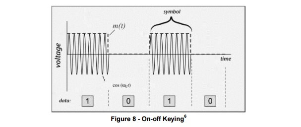
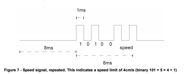
"The speed limit signs will transmit this speed using pulsed Infra-red, on a carrier frequency of 38kHz using on-off keying (the binary state of 0 means no signal, while 1 means maximum carrier amplitude – see Figure 8).The speed value will be transmitted at 1kbps, in a format shown in Figure 7. The signal is repeated, with 8ms of off-air time and 8ms on-air time. This 8ms of on-air times consists of an 8-bit code, with the first five bits being a pre-amble, 10100, and the final three bits containing the speed encoded in binary (plus one, so that 000 = 1cm/s and 111 = 8cm/s)."

Figure 7:
7mZdQVf.png


Figure 8:
hCxMGNX.jpg


So what have I done so far?
Not much :(

I am using an Arduino Uno and so far I have bought an IR Receiver and checked that it is working using this Test.

On top of that I have read through this article and have successfully run this example using my TV remote.

I have also played around with a few IR Libraries which print a hexadecimal value for the buttons I press on the remote.


What I am having trouble with is how to interpret the output of the Ir Receiver. It looks a bit like binary but outputs of running the above Example are really confusing me.

If anyone could explain how to interpret the output or link me to a quality resource I could read to further my understanding I would really appreciate it. I am quite lost at the moment.
 
" .... The signal is repeated, with 8ms of off-air time and 8ms on-air time. This 8ms of on-air times consists of an 8-bit code, with the first five bits being a pre-amble, 10100, and the final three bits containing the speed encoded in binary (plus one, so that 000 = 1cm/s and 111 = 8cm/s)."


You have 8 bits received every 8 millisecond followed by 8 milliseconds of silence.

The first 5 bits are a "preamble". Putting it simply, consider it as a "signature" of the transmitter so that you know that the signals received are from the right source.

The preamble will also serve as a "sync" .... but we will ignore it here.

The next 3 bits are just a binary information of the speed with an flat offset.

You interpret the output this way"

* confirm that the first 5 bits are 10100.
* convert the next 3 bits to decimal ( it will vary from 0 to 7), add 1 (offset) to get 1 to 8.

What is important here is to realise that the 8 bits are received in the reverse order.

So if the transmitter intends to send information that the speed is 4 cm/s, it will first deduct 1 to make it 3, and encode it as a 3 bit binary 011.

It will introduce the preamble 10100 and follow it with the 3 bit value 011.

It will, therefore, transmit 10100011.

The IR receiver will get it as 11000101

So you need to count the bit order as received and NOT as stored in the received register.

To interpret the received data, ensure that the last 5 digits are 00101, give weightage to the first bit as 2, second as 4, third as 8. This will give a decimal value 3, add the offset 1 to give the result 4 - the original transmitted information.

Hope I haven't confused you :D

Wow this is a great explanation, really helped me understand what is going on :D Thank you very much.

At the moment I am struggling to get my head around the short time periods. How would I read the signal every 8 milliseconds, or even set one value of an array every 1 millisecond? I don't feel I would be fast enough to keep up with it. I am thinking of continually reading in the signal as 1's and 0's then converting them to decimal values and comparing them to see if the signal has changed, then clearing the array in the 8 millisecond off time. Sorry if I don't make any sense I think I have confused myself XD

Also I am keen to test my solution but I am not too sure how I would go about setting up the scenario?
I am thinking of using an Infrared LED and pulsing (or not pulsing) it every millisecond for 8 milliseconds followed by 8 milliseconds of 'off-time'. However I am once again stuck at how to process at such a fast speed, wouldn't it take longer than millisecond to check a condition and send the signal to the LED?

Sorry if I am being completely ignorant, but thank you very much for all your help so far, really appreciate it :D
 
A quick reply.

You intend to use a Arduino Uno. Even a 1 millisecond is plenty of time for it do not only what you want, but lot more.

I have'nt used the Arduino Uno, and don't know its software. I can't help you on that.

The process would be:

You generate a 1 KHz clock in your Arduino Uno by software. This clock gives you the mSec timing . You can also generate a 1KHz external clock using a 555 (these clocks are accurate enough for your purpose) That gives you the timing reference.

Wait for the first bit transition from L to H, start storing it in a 8 bit shift register.
Once the 8 bits are stored, you have plenty of time to analyse the bits, flash your LED's, take action to speed up or slow down your car.

Remember - today, we talk about microseconds and less :rolleyes:, millSeconds is plenty of time.:D

Awesome, thank you very much for all your help :D
 
Just one minor point that could need clarification - the project explanation does not explicitly state whether the speed code is transmitted with the LSB first or last. The examples given are similarly vague (000, 111, 101). Is this just an oversight? Or is it a wicked deception meant to confound those who make quick assumptions?
 
Just one minor point that could need clarification - the project explanation does not explicitly state whether the speed code is transmitted with the LSB first or last. The examples given are similarly vague (000, 111, 101). Is this just an oversight? Or is it a wicked deception meant to confound those who make quick assumptions?

Yes, you have a point.

I was trying to explain the Intrepretation process and my example presumes that it's LSB first.

If it's the other way round, then the "preamble" would be the First 5 bits as 10100, the speed as the Last 3 bits with the weightage increasing Right to Left.
 
Yes, you have a point.

I was trying to explain the Intrepretation process and my example presumes that it's LSB first.

If it's the other way round, then the "preamble" would be the First 5 bits as 10100, the speed as the Last 3 bits with the weightage increasing Right to Left.

Considering I will not have a chance to test my under exam conditions(Therefore it has to work on the day, first time or nothing), is there a 'surefire' way of knowing whether the least significant bit will be first or last?
I have booked a lab for tomorrow so I will hopefully be getting some work done, specifically trying to replicate my own accurate test environment.
 
Look for the "preamble pattern" :

If the 8 bits received are:

10100xxx then it is MSB first - xxx weightage R -> L

xxx00101 then it is LSB first - xxx weightage L -> R

BUT if the xxx happens to be 101, you would'nt know :eek:

So run the car in more that one "speed" zone and study the pattern. That will tell you which 3 bits are xxx because it will have to be either 10100xxx or xxx00101

The preamble will be the same (or has to be :rolleyes:) in either case.
 
Actually this does not look ambiguous to me. It is stated that the preamble is 10100 and the timing sequence shows the bits in that order, so it is high bit first.

Bob
 
Top