Maker Pro
Maker Pro

Need help with Warning LED indicator for redundant power supply.

I am having trouble with this and am looking for a simple solution to my problem, I have a single battery supplying 2 switching voltage regulators, the output on each regulator is 12v, 3 amps. I have them wired in parallel as the load requires 12v. The key is I need redundancy so if one voltage regulator fails the other will continue to supply power.. What I am trying to accomplish is adding 2 leds to indicate a failure, 1 for each voltage regulator to indicate that this regulator Is working and outputting 12v. If I see one of these LEDS turn off I know that corresponding voltage regulator Is no longer functioning. Can anyone help me out with this?
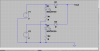
I have attached a simple circuit diagram Minus the indicator LEDs. I already have 12v LEDS on hand.
Thank you!
Jason
 

Attachments

  • Untitled.jpg
    Untitled.jpg
    25.5 KB · Views: 108

Harald Kapp

Moderator
Moderator
Welcome to electronicspoint.

It is not good practice to connect two voltage regulators in parallel without a means of protection. The regulator with a slightly higher output voltage will drive the bulk of the load current while the other sits more or less idle.
You should provide a means of load sharing (typically a small series resistor in the output of each regulator before paralleling).
You should also provide protection against reverse supply (e.g. diodes) so no current can flow from the good regulator into the output of the bad regulator in case of a failure. Of course, you'll have to compensate for the voltage drop across the diodes an d the resistors, so the nominal output of the regulator has to be set to 12V + voltage drop.

Google "paralleling power supplies" or read this for some information.
 
From the OP post, it seems that each power supply will have to handle the complete load.

Though Load Sharing is advisable, it does not seem to be necessary.
Isolation Diodes should do the job, taking care to ensure that the supply output is trimmed to take care of the voltage drop of the diode.

For the indication of Failure, we need to define "Failure". If complete shut down of the PSU is a failure, then there is no problem of indicating it. Simply put LED with a Protection diode across the Isolation diode. This will glow when the PSU is down (being fed from the other PSU. Will need to adjust the series resistor for current limit).

But if Failure means Reduction of Voltage, then the setup becomes more complex since it will mean monitoring the Supply Voltage AND Current. Then the issue of Load Sharing comes in as mentioned in the earlier post.
 

Harald Kapp

Moderator
Moderator
Though Load Sharing is advisable, it does not seem to be necessary.
In principle you are completely right: load sharing in this case is not necessary. However, reducing the load under normal operating conditions to ~1/2 per regulator reduces stress (heat) on the regulator and its components which in turn will serve to increase reliability.
 
Thank you for the replies. To elaborate on this,the load I am driving is 2 amps peak. I am going to use (2) switching voltage regulators that output exactly 12v each and have a nominal 3amp output. I would like a led to indicate status of each regulator ( led on indicates that corresponding regulator is functioning properly.) If one led turns off I know that I have a fault in the regulator. I like the idea of load sharing but I suppose it is not absolutely necessary. Can someone direct me to a way of accomplishing this task. I am not asking for anyone to do the work for me just possibly help me along a bit so I can actually learn more.
Thanks everyone
Jason
 
I was on my phone when I typed that last message. I must have missed his original reply. I will take that advice and give it a try. Thank you everyone!
 
would you guys suggest placing the series protection diodes on the negative or positive side of the output? I unfortunately am still having issues getting the LEDs to function properly.
Jason
 

Harald Kapp

Moderator
Moderator
Always on the positive. It is customary to have a common ground (-) for all circuits, so there should ideally be no circuit element in the ground connection (other than plain wire).
 
Thanks Harald,
This is what I thought. So to do the LED indication I would need to put a diode on each of the regulators positive outputs, (2 regulators, 2 diodes in series on positive rail of output.)
ramussons states "Simply put LED with a Protection diode across the Isolation diode. This will glow when the PSU is down (being fed from the other PSU. Will need to adjust the series resistor for current limit)."
Could you guys explain this in laymans terms, not sure I am picturing this the correct way in my head. I am quite new to this exciting world of electronics, please don't be too hard on me.
Jason
 
I just discovered LTSpice Harald, viewing your resources tab Thanks for posting that!
I am going to tinker with this hopefully it will simulate what I am trying to accomplish. So I may translate it to a breadboard.
 

Harald Kapp

Moderator
Moderator
ramussons states "Simply put LED with a Protection diode across the Isolation diode. This will glow when the PSU is down (being fed from the other PSU. Will need to adjust the series resistor for current limit)."
This is not sure to work, depending on the internal circuit of the regulator. I propose a different setup:
unbenannt-png.19714

Here D3 and D4 are LEDs, R1 and R2 limit current through the LEDs. As long as the associated power supply is o.k., the respective LED will light up. In case of a failure, the LED will be off - assuming the failure is a complete loss ouf output voltage. If you want to monitor more complex failure scenarios, you will need a more complex circuit.
 

Attachments

  • Unbenannt.png
    Unbenannt.png
    21.4 KB · Views: 192
Harald,
I tried the above circuit and it did not function as intended. Both leds stayed lit when either power supply was shut down. im not sure why, possibly the diodes I used? I used 1N5404 diodes for D1 and D2. I breadboarded it exactly as shown and checked it 3 times. If I separate each ground on the regulator output (not tied together) The respective led will dim when I remove the input positive or negative.
Thoughts?
 
I am wondering if it would just be easier to just keep the isolation diodes and then use a transistor on the backside of the diode to trigger a base that turns led on, if regulator fails then it would shut led off. But I am wondering how reliable it would be as I think it could give me a false reading depending on how the regulator failed.
 

Harald Kapp

Moderator
Moderator
I breadboarded it exactly as shown
Allow me to have my doubts. When you turn off e.g. V1, there is no way for D3 to receive power. Are you really sure D3 is on the anode side if D1 (and D4 on the anode of D2)?

I am wondering if it would just be easier to just keep the isolation diodes and then use a transistor on the backside of the diode to trigger a base that turns led on
What's easier in using an addtional transistor compared to a simple LED-resistor circuit?

But I am wondering how reliable it would be as I think it could give me a false reading depending on how the regulator failed.
You'll have the same issue with the LED-resistor circuit.
 
I am positive each led is on the anode side of each diode (the side of the diode without the stripe.) could it be a problem with the particular diode I am using(1N5404)?
 

Harald Kapp

Moderator
Moderator
Not if the diodes are working properly. They are rated at a reverse voltaeg of 400V, more than enough for your project. Can you post a legible photo of your breadboard setup?
 
Yes I can, but I will have to wait until tomorrow . I must go to sleep for work in the morning. I will post some pics tomorrow when I get home!
Thanks Harald!

Jason
 
Top