You shouldn't be surprised!
All that Lei needs to realise is that the power required is the sum of the power dissipated in every load.
Yes, that's the basic point here. Calculate the power used by each load, and add them all together.
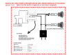
For simplicity we assume that the 12V 1A power supply is 100% efficient,
I shouldn't have assumed that. I really don't know what Lei wants this information for. If he wants to know the total power consumed from the mains, then he should factor in the losses in the 12V supply.
We also assume that the power consumed is what is written on the label.
Yes, and that would normally be the input power. But with an output voltage of 28V, if the 7W is the
output power, not the input power, that's an output current of 250 mA. Coincidence?
All of these power ratings will be steady state, and/or averaged over time, so we can't say instantaneously what the exact power demanded by the circuit will be. But over a reasonable time (and this may be 1 cycle of the mains) it will average out to some value.
Yes, nicely put.
Kris gave a perfect example above where the power is zero for most of the cycle and then jumps up to some higher amount (which itself varies) for a small part of the cycle. Pretend that this is the V/I graph for one of your 7W lamps. For that small time in the middle the lamp may be consuming 21W, but it does so only a third of the time, so the average power is 7W. There are other odd circuits which store power in one part of the cycle and give it back in other parts. For those the power can actually be negative during part of the cycle.
I was assuming that the lamps are powered with DC from switching supplies, so the funny current waveform would apply at the mains input to the supplies.
I was going to ask you to explain, with this funny current waveform, how this relates to VA vs. watts, and how you would specify the power consumption of a power supply like that, in terms of what would be measured by your household electricity meter.
Also note that Kris is giving the average current. If the device draws power in spikes, the maximum current might be higher (and even if it draws it "evenly", it may vary through the AC cycle).
Right. If the load is non-linear, like the input to a switching supply without power factor correction, that's going to happen.
In most cases we can ignore this, but it may be worth bearing in mind that for this device the maximum current during some period might be 50% higher than this, or several times higher, depending on the nature of the load. This is not something that can easily be calculated from the sort of block diagram you're using.
Right. You would need to know some detail about all three power supplies.
In most cases for things other than loads (i.e for cable, power supplies, switches, etc.) any mention of current is typically an upper limit that you should not exceed, not what will or must be used.
Or in the case of a power supply, it would be an upper limit that the power supply would not exceed, except during power-up. It wouldn't be the RMS current, or the mean absolute current.
(re Sir) I'll second that. We both have names and neither of us (to my knowledge) wear shiny armor whilst riding out on horseback to kill people.
")
And neither of us have been tapped on the shoulders by a sword held by a monarch. "Sir" is a mark of deference and respect, and a word I occasionally use when talking to old people, but being called Sir makes me uncomfortable. When salespeople in shops call me Sir, I call them Sir or Ma'am in return!