Maker Pro
Maker Pro

Need help with a Wacom Cintiq 21UX monitor (Reverse polarity applied) - SOLVED

Hello all,

I have a display board at hand (attached a picture below) with Several functions listed below:

1. It has 2 x 12 volt rail input that is powered from a power brick that is rated 12 v with 6 amps max.
2. It has a small keypad and Power Switch input
3. It has I/O power output
4. It has CCFL Backlight Circuit output
5. It has LCD circuit output
6. It has DVI output

It is a custom made Display Driver that runs a Genesis GM1601-LF chip.

Something happened to this unit and unfortunately I was not there when it happened and everyone who was there is blaming the other for what happened to it so its impossible to get an accurate account of the situation but, what I understand is that a false connection was made to the power and either the 12V rails were swapped (+ and -) or another power brick was used on the unit and whatever the reason was now it is not working.

I check the I/O power output for another board that on the circuit and no power arrives at those rails. I have limited electronics knowledge (I can solder and make small circuits) but I want to fix this thing. My questions are:

1. What parts of it should I check to find faults?
2. Could this just be a diode problem or a problem with a part that I can replace?
3. Any other thing that comes to mind?

Thank you in advance.

Baris

wacom.jpg
 
Last edited:

(*steve*)

¡sǝpodᴉʇuɐ ǝɥʇ ɹɐǝɥd
Moderator
Does it do anything at all?

If you're really lucky there may be fuses diodes to protect against reverse polarity.

If you're really unlucky you may have damaged almost every IC on the board(s)

Start my tracing the 12 volt rails and hope (it may be a vain hope) that there is a surface mount fuse on each rail that has blown. (but I can't see anything)

Does it draw any power at all from a correctly applied 12V rail?

The components to the left of the 12 V connector appear to be a switchmode regulator. This is probably to supply either 5V or 3.3V to parts of the board that require it. It's quite probable that the IC has failed, but (again, if you're lucky) the switchmode regulator *may* have protected the 5V part of the circuit (depends on whether reverse voltage holds the main switch device on or off).

However anything powered directly from 12V (assuming no fuse & reverse protection) is going to have had to fend for itself. I wouldn't be overly confident.
 
What steve says.
Check for 12V on the input power contact and on the first horizontal capacitor. If ok then check for 5V on the second horizontal cap. (my guess)
If those are ok then check the voltages on the upper & lower pin of the presumed 3.3V regulator. The nearby screw seems to be a proper ground point btw.
The power switch may be responsible for switching on/off some circuit (CPU, backlight, &/or I/O output.
 

Attachments

  • wacom.jpg
    wacom.jpg
    153.4 KB · Views: 1,032
Thx for the replies guys, here is what I found:

Steve,

I tested the small keypad and power switch input channel and found that I have power there. The voltmeter shows me 6.5-6.7 Volts on some channels, I dont know if its the right amount but its something.

I also have power at the CCFL output port, 12 volts on some of the channels.

I dont have any power at the LCD circuit output port, I dont know if thats because somethings wrong there or if its because the LCD circuit doesnt get any power without the device being turned on.

I have no power at the I/O output port, unfortunately.

Resqueline,

From your marking on the image, I tested the 12V capacitor and its at 12V when power is applied. I tested the one that you marked as 5V but the voltmeter reads 0 on that one.

The "power switch", "3.3V regulator" and the "crater", not sure about those, dont really know how to test them. The crater doesnt really look like a crater, more of a surface mark of a pen. How can I test the other parts of the board? Should I take the big diode out and test that as well?

Thx.
 

(*steve*)

¡sǝpodᴉʇuɐ ǝɥʇ ɹɐǝɥd
Moderator
1) Measure from the -ve rail of the 12V power supply to each pin of what Resqueline believes to be a 3.3V regulator. Readings of 0, 3.3 and 5 (in some order) may be reasonable.

2) Can you get a close up photograph of the "cratered" IC? This is the sort of physical evidence you sometimes see of catastrophic destruction of a chip. It might also be (as you describe it) a pen mark.

3) have you measured the power this now draws from the 12V PSU?

NOTE: I can't be sure if the 12V input is 2 wires for each of 0V and 12V, or if the power supply is split. (+/- 12V). Does the connector have 2 colours of wires (say 2 each of black and yellow) or does it have something else (say 2 black, a yellow and an orange)?

The voltage measurements should generally be with reference to the black wires (if the wiring uses a common convention).
 
Hello again,

I took the measurements, it can be seen on the attached image. All the measurements are off the V type and (NC) means Not Connected.

The power coming in consists of two black and two white wires. Both of them carry 12V.

I have not measured the power this draws, how should I go about doing that the healthy way?

Thanks.

IMAG0001_measured.jpg
 
Power (= current) measurements can be a little tricky since it usually involves disconnecting one wire and inserting the multimeter in series there.
Try to read the number(s) on the lower left chip (next to the power plug), and also measure the voltage on its pins (if you have a narrow/sharp enough test probe).
One secondary aspect that could be interesting is if any voltage anywhere toggles as you push the power button, but that can wait.
 
I measured the chip by the power input and I got measurements varying between 12,03-11,00 V on all legs, so I guess thats working. I also took a picture of the back of the card, there are a few more IC's here and small capacitors and resistors.

I measured all the IC's, and some of them I read Voltage but, some I didnt. I was not able to measure the Current that the whole card draws because my multimeter is rated at 2A Max. and according to the power brick, this thing can draw 6A Max. I guess so didnt want to risk the multimeter:(

I also couldnt get a picture of the "crater" IC but, I am pretty certain that its not cratered as I can still see the printed writing coming through under the black mark if I look at it real close.

What Should I check next? See if the power switch makes any difference?

Thanks guys!

img_back.jpg
 
I was able to take some macro pictures of the "crater" chip that Steve was asking about before.

DSC_3242.jpg

I also took some macro pictures of the chip that Resqueline asked me to measure last time. Even though the chip gave signs of life (measurements mentioned in last post) I see some marks on it that I am not sure but, do look like craters. Here they are for you to judge.

DSC_3245.jpg
DSC_3243.jpg

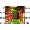
I am also adding the measurements from last post here on the image.

DSC_3245_mod2.jpg
 
Last edited:

(*steve*)

¡sǝpodᴉʇuɐ ǝɥʇ ɹɐǝɥd
Moderator
One thing is certain (well, pretty certain). That is the switchmode regulator is not working. Please follow Resqueline's advice to read the part number of the small 8 pin device to the left of the power connector. (edit, OK I think we can read it now)

I am pretty sure that this will require replacement in order to get the 5 or 3.3 volt rail that it generates -- and that presumes nothing else in the regulator is destroyed (a reasonable bet though).

Nice photos. Physical damage is not usually visible on damaged chips, if it is you know that the destruction was catastrophic :-( I'm pretty sure the damage to that regulator is catastrophic.
 
Last edited:
Yep, I wouldn't expect those holes to be air bubbles from the moulding of the IC..
I fail to immediately recognize the numbering system on that chip though..
Having almost full voltage on all (but one) pins is not a sign of it working.
 

(*steve*)

¡sǝpodᴉʇuɐ ǝɥʇ ɹɐǝɥd
Moderator
My fear is that with all pins (except presumably the ground pin) being at or near 12V, the switching transistor would likely be turned hard on.

That would expose everything following to the full supply voltage (bad).
 
Last edited:
Im reading AIC1578PS and it seems to be a "High-Efficiency, Step-Down DC/DC Controller" as the pdf document spec sheet puts it. I dont know if I can find the exact one but, maybe I can find a replacement, any ideas?

Also, if this chip is fried and its giving higher than rated numbers on its other legs, does that mean other stuff might be fried as well and how to go about finding those?
 
Last edited:

(*steve*)

¡sǝpodᴉʇuɐ ǝɥʇ ɹɐǝɥd
Moderator
Yes, it is quite possible that a large number of devices are damaged.

Anything CMOS would most likely have suffered from large currents flowing through protection circuits. This may, on its own, have destroyed devices without even considering what reversed voltages do to the rest of the chip.

Read my first post again. Clearly there was no protection against reversed power supply connections. So you're at the point where you might wonder which chips are NOT damaged, rather than which are.

But maybe I'm just a pessimist. Lets see what others have to say...
 
Ok, let me try and understand this, if I replace all the IC's and the capacitors, I might have a chance at getting this thing to work? What are the chances of the Samsung memory and Genesis GM1601 chip being damaged from all of this?
 
The built-in (parasitic) diode in the P-channel switching transistor would conduct a negative voltage into the circuit but the external schottky diode would short this to ground.
So I have good hope for both the transistor (ohm it out) and the rest of the circuits (but no guarantee).
The hardest part would be obtaining the IC (I doubt you'll find a replacement part) and then doing the solder job.
 
Incredible.. :) I doubt you'll need to change anything else, just ohm the lower left transistor that you marked 12,03 0,01(NC) 11,70 for shorts between any of the 3 pins.
 
Hehe, no, you put your multimeter in the Ohms position and probe the transistor (between pins, not to ground) without applying power to the circuit. 0 ohms = faulty.
 
Top