Maker Pro
Maker Pro

Need help to build police siren/LED flasher

Dear all,

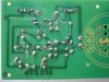
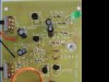
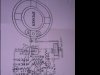
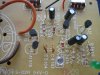
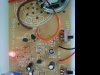
I recently bought a ready made Project kit with circuit board, parts and schematic attached
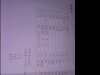
from a China company. The kit is for LED flasher and police siren; the schematic and parts list which I attached.

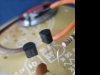
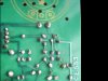
The problem is the LED 1 & 2 does not flash or any sound from the speaker after I done the soldering of parts. The kit works on a 9V battery.

Any help and guidance to fully function this project is appreciated.
 

Attachments

  • IMG_0041-sirenback.JPG
    IMG_0041-sirenback.JPG
    48.4 KB · Views: 544
  • IMG_0042-sirenfrt.JPG
    IMG_0042-sirenfrt.JPG
    37.8 KB · Views: 615
  • IMG_0031-sirenschematic.JPG
    IMG_0031-sirenschematic.JPG
    16.3 KB · Views: 585
  • IMG_0032-sirenparts.JPG
    IMG_0032-sirenparts.JPG
    15.3 KB · Views: 567
  • IMG_0033-sirenschematic.JPG
    IMG_0033-sirenschematic.JPG
    28.4 KB · Views: 609

(*steve*)

¡sǝpodᴉʇuɐ ǝɥʇ ɹɐǝɥd
Moderator
Your construction is not real good, it is possible that the untrimmed leads on the bottom of the board are shorting something. Also the resistors are normally placed flat against the board.

I don't have time at present, but someone may be able to check your resistors are correctly placed. Without images from the side we can't check the transistors.

It is also possible that your soldering is bad enough to have made a very poor joint, but that normally results in intermittent operation.
 
1. Trim those leads!
2. The solder should have flowed to cover the entire pad if done correctly. Put some flux on them and reheat until each solder joint looks like a little cone, covering the pad and going up the lead.

Bob
 
Dear Steve & BobK,

Will take your advice to trim those leads and re solder those spots that do not cover entire pad. Hopefully to do this by the weekend and post good result.

To KJ6EAD,

I watched the "How to solder" video and gain more knowledge on soldering properly.

Did anyone check to make sure the schematic is correct and workable since I am still new
on reading schematic.

Thanks for the above help and kind assistance.
 
Here's a clear copy of the kit data sheet from the manufacturer. It looks like a typical astable multivibrator driving LEDs and triggering an audio oscillator. Post new pictures of the board when the suggested corrections are made and we'll look for any other problems.

http://us.100y.com.tw/pdf_file/A026.pdf
 
Last edited:
Dear all,

Last night out of curiousity and managed to find time using a multimeter diode function
to test capacitor C1815 label as TR1(Q1), TR2(Q2) & TR3(Q3). I connected multimeter
negative black probe(-) to one lead label as 1(refer paint picture "capHA026), then positive
red probe(+) to other lead and achieved the below reading:

On Q1: -1 (lead 1) & +2 (lead 2)= 1 (over limit ?)
-1 & +3 (lead 3) = 785
-2 & +1 = 1
-2 & +3 = 698
-3 & +1 = 1
-3 & +2 = 1

On Q2: -1 (lead 1) & +2 (lead 2)= 1 (over limit ?)
-1 & +3 (lead 3) = 696
-2 & +1 = 1
-2 & +3 = 693
-3 & +1 = 1
-3 & +2 = 1

On Q3: -1 (lead 1) & +2 (lead 2)= 1 (over limit ?)
-1 & +3 (lead 3) = 698
-2 & +1 = 704
-2 & +3 = 704
-3 & +1 = 1
-3 & +2 = 1


On Q4: -1 (lead 1) & +2 (lead 2)= 1 (over limit ?)
(A1015) -1 & +3 (lead 3) = 1
-2 & +1 = 1
-2 & +3 = 1
-3 & +1 = 699
-3 & +2 = 699


What are the above results mean ? And possibly point out which cap is NPN
and which is PNP, and where to locate emitter,collector or base.
Need great help here as I am very new to these concepts.

Thanks for the help.
 

Attachments

  • IMG_0065.JPG
    IMG_0065.JPG
    47.2 KB · Views: 408
  • IMG_0066-Q1.JPG
    IMG_0066-Q1.JPG
    24.2 KB · Views: 429
  • IMG_0067-Q2.JPG
    IMG_0067-Q2.JPG
    30.9 KB · Views: 472
  • IMG_0068-Q3.JPG
    IMG_0068-Q3.JPG
    24.3 KB · Views: 405
  • IMG_0069-Q4.JPG
    IMG_0069-Q4.JPG
    23.7 KB · Views: 405

KrisBlueNZ

Sadly passed away in 2015
Q1~4 are transistors, not capacitors. Q1~3 are NPNs, type 2SC1815 or 2SC945, and Q4 is PNP, type 2SA1015. (The "2S" prefixes are often omitted.)

At first glance, it looks like you've got the components right, but all those leads underneath are bound to be shorting onto each other, and onto other pads. As others have said, you need to trim them flush with (or just slightly above) the solder. Also, your solder joints don't look very healthy. Are you using 60/40 solder with rosin core? What type of soldering iron are you using? It's important to make your joints quickly and remove the heat; if you leave the heat on too long, the joints will go grey and crusty like that.
 
Hi,

I took advice of trimming the leads, then resolder those joints not properly done to make
sure the solder cover the pad fully in cone shape. Also change transistor Q3 (C1815) and replace a new one from my stock. Then, I plug in battery and switch on, the LED lights flash (refer photo) and the siren also sounds ! Thank you all for the help to complete this project.

BTW, currently using a 40 watt soldering iron but not sure what type of solder.
Anyway, thank you as I learn better soldering method from your advice.

Still not too sure on my previous attempt to do some diode test on transistor such as on
C1815 label as TR1(Q1), TR2(Q2) & TR3(Q3) whereby I connected multimeter
negative black probe(-) to one lead label as 1, then positive red probe(+) to other lead and achieved the below reading:
On Q1: -1 (lead 1) & +2 (lead 2)= 1 (over limit ?)
-1 & +3 (lead 3) = 785
-2 & +1 = 1
-2 & +3 = 698
-3 & +1 = 1
-3 & +2 = 1

On Q2: -1 (lead 1) & +2 (lead 2)= 1 (over limit ?)
-1 & +3 (lead 3) = 696
-2 & +1 = 1
-2 & +3 = 693
-3 & +1 = 1
-3 & +2 = 1

On Q3: -1 (lead 1) & +2 (lead 2)= 1 (over limit ?)
-1 & +3 (lead 3) = 698
-2 & +1 = 704
-2 & +3 = 704
-3 & +1 = 1
-3 & +2 = 1

Does the test mean Q3 transistor is faulty ?
To save trouble, I desolder this transistor Q3 and replace a new one.
I guess this solves the audio no sound earlier on.
 

Attachments

  • IMG_0072-trim.JPG
    IMG_0072-trim.JPG
    37.2 KB · Views: 412
  • IMG_0074-lite.JPG
    IMG_0074-lite.JPG
    40.8 KB · Views: 359

KrisBlueNZ

Sadly passed away in 2015
That's good news. That solder doesn't look very healthy to me. Is it lead-free solder? Are there any markings on the reel?

A 30 watt soldering iron would be better, and a temperature-controlled iron is best, but 40 watts should be alright. Make sure you're not holding it on the joint for longer than a few seconds. Ideally the total contact time for the soldering iron should be less than one second, and you should never re-melt a connection. If you have to remake a connection, remove the old solder first and keep the total contact time less than one second for the new solder.

If the thing works, there's not really any point testing the transistors. For future reference here are the basic checks you can do using a multimeter on diode test range, and the results you should expect with standard bipolar junction transistors.

FIrst figure out the pinout of your transistor. Both types use the Japanese pinout at the left of this diagram.

attachment.php


Now measure between each pin and the other two pins, with the probes one way round then the other. You should measure open circuit (your meter will indicate "1" meaning overload) for all measurements except two:

For NPNs:
Positive lead to base and negative lead to emitter should read about 600 mV
Positive lead to base and negative lead to collector should read about 600 mV.

For PNPs:
Negative lead to base and positive lead to emitter should read about 600 mV
Negative lead to base and positive lead to collector should read about 600 mV.

The exact voltage is not important, and it's not important that both measurements are the same.
 

Attachments

  • TO-92 aka TO-226 transistor common pinouts.gif
    TO-92 aka TO-226 transistor common pinouts.gif
    48.6 KB · Views: 39,266
In the above tests, a "0" reading and on some meters a beep tone indicate a short. This is a typical failure mode for BJTs (bipolar junction transistors).
 
Top