Maker Pro
Maker Pro

Need help adding a Line-in to a Roland MT-300s (MIDI Music Player)

Hello All,
I have a nice Roland MIDI player (MT-300s) and would love to add a Line-In to it (2xRCA connectors in the back) but I'm not exactly sure how to do it and wanted to ask if someone can help me figure this out.
I managed to download the "service notes" so here are my "thoughts":

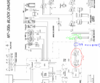
Looking at the diagram below, I think (correct me if I'm wrong) the new Line-In should be inserted where is marked in green and add a couple of diodes right before it (marked in blue) so the signal doesn't go in the wrong direction. (?)
Does the internal signal at that point is Line level ? coming from the D/A, correct? Don't know what are those other two components "I/V" and "LPF" ? (Low Pass Filter? Can't be, It has to be something else).
OR, should I insert the Line-in before any of those two components?

upload_2019-9-24_23-55-12.png

Now, this is the diagram of the actual Volume Board:
upload_2019-9-25_0-7-22.png
I really don't know which pins are the ins and outs to the volume board, obviously we are looking for the INS, +L +R, also which pin would be the ground?, I guess I can find it with a multimeter taping the chassis, correct?

Also, I want to add a switch to have two options: Line-In mixed with player, and, Line-In only.
Is it "electronically correct" to have the two signals wired together?

I really appreciate anyone's time just reading this,

Thank You,
Dusko
 

Attachments

  • upload_2019-9-24_23-18-54.png
    upload_2019-9-24_23-18-54.png
    252.1 KB · Views: 1

Harald Kapp

Moderator
Moderator
Welcome to EP, Dusko.
add a couple of diodes
Definitely not. Diodes wil rectifiy the signal and hgeavily distort it. You'll have to insert a mixer circuit as shown e.g. here or here.
Is it "electronically correct" to have the two signals wired together?
No, you should not wire two signal sources together without any form of mixin circuit (could be active or passive). A simple method of turning off the external line-in input is by switching the respective input of the mixer (here lin-in is connected) from line-in to gnd using a change-over switch (also known as double pole double throw DPDT switch - double pole for stereo, single pole for mono).
 
Hi Harald,

first, Thank You for taking the time, that helped me a lot. I don't know why I wanted to mix the two signals, it is pointless, so will go for a switch to select between Line-in OR internal signal. What type of switch would you recommend?
Now, is cutting the signal at the point I marked in green the correct place to do it?
I don't think you will be able to identify which pins are L,R (inputs) in the Volume Board diagram, correct?.
I'm curious about something, looking at the first diagram, the Mic-In ends up merged (wired) with the internal Line signal which is what I thought I can do with the Line-In, then it goes into a "Mix", don't know what that "mix" is mixing since it looks to me that the two signals are coming in together already. (?) BUT, now I'm realizing that since it is a block diagram, is just showing basic "flow", correct?

Trying to figure out things in the "Circuit Diagram" I get lost, so here is a link to the "service notes" pdf document in case someone wants to take a look at it.
https://www.dropbox.com/s/f1xa8hdpcwf0bcc/MT-300s Service Notes.pdf?dl=0

I'm not quite sure what level of experience are you expecting in this forum, this may be very boring for experts, I'm not as knowledgeable with electronics as I thought I was and that you expected me to be, so no hard feelings if nobody cares about my project.

Thank You,
Dusko
 

Harald Kapp

Moderator
Moderator
What type of switch would you recommend?
Any double throw doublke pole switch will do. Preferably one with a shielded case - if you can find one.
Now, is cutting the signal at the point I marked in green the correct place to do it?
Yes, it is one place to splice the new inputs in. However, you'll have to measure the signal levels of the original circuit and match the levels of the input signals to those internal levels (attenuate or amplify). Or you risk distortion.
I don't think you will be able to identify which pins are L,R (inputs) in the Volume Board diagram, correct?.
Not from this block diagram.
BUT, now I'm realizing that since it is a block diagram, is just showing basic "flow", correct?
Right.

I'm not quite sure what level of experience are you expecting in this forum, this may be very boring for experts, I'm not as knowledgeable with electronics as I thought I was and that you expected me to be, so no hard feelings if nobody cares about my project.
Levels vary wildly. No need to have bad feelings. However, as you are obviously a novice in electronics, expect a steep learning curve.
 
I have found that ordinary high current power switches have silver contacts that fail in a short time when used with very low power audio signals because the silver tarnishes (high power cleans away the tarnish). Therefore I always use switches with gold contacts (they cost the same as power switches).
 
I would suggest taking a non-destructive route and building a converter for the Mic input that's already present, or embedding the circuit internally with a bypass switch:
 
Top