Thanks for helping me out in my first thread.
Need your help again try pointing out a right component for specific task, this time in a bit different configuration, used to solve a problem with ground potential.

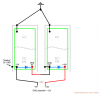
Normally when making these series configurations, the ground potential at the DC output will turn out be -12V.
Now with some chargers in the Radio Control world, they are also made with a USB port, so you can hook up a computer in the setup, and do things like data logging.
Especially with desktop pc's, these are always grounded, with ground potential of 0V.
If the example says this 0V ground potential have directly connection from the USB cable of the computer, to the RC charger and the DC GND output of the power supplies, you create an unexpected ground loop, a situation that could cause malfunction to the USB connection, probably do damage as well. The guidance to avoid this problem tells to remove DC ground internal from the metal case, this time in both power supplies. Then solder a filter capacitor from DC GND to the metal case and one from +12V to metal case. The capacitors then damp high frequencies coming from the AC, that would otherwise do harm to the USB connection and to my knowledge also recover some protection that you normally would lose by "floating" the DC GND completely, This should then make the units safer. If the DC GND is connected to the metal case, you face the issue with the ground potential difference, because the ground potential will be -12V.
Again, the source lacks specifications on the filter capacitors. What should I look for?
Another question for the guys who can answer:
What would it likely change on safety, when adding these capacitors rather than having DC GND to ground? Anything to be concern about?
Attached another png with the DC GND connected to ground as example.
Feel free to ask questions.
Need your help again try pointing out a right component for specific task, this time in a bit different configuration, used to solve a problem with ground potential.
Normally when making these series configurations, the ground potential at the DC output will turn out be -12V.
Now with some chargers in the Radio Control world, they are also made with a USB port, so you can hook up a computer in the setup, and do things like data logging.
Especially with desktop pc's, these are always grounded, with ground potential of 0V.
If the example says this 0V ground potential have directly connection from the USB cable of the computer, to the RC charger and the DC GND output of the power supplies, you create an unexpected ground loop, a situation that could cause malfunction to the USB connection, probably do damage as well. The guidance to avoid this problem tells to remove DC ground internal from the metal case, this time in both power supplies. Then solder a filter capacitor from DC GND to the metal case and one from +12V to metal case. The capacitors then damp high frequencies coming from the AC, that would otherwise do harm to the USB connection and to my knowledge also recover some protection that you normally would lose by "floating" the DC GND completely, This should then make the units safer. If the DC GND is connected to the metal case, you face the issue with the ground potential difference, because the ground potential will be -12V.
Again, the source lacks specifications on the filter capacitors. What should I look for?
Another question for the guys who can answer:
What would it likely change on safety, when adding these capacitors rather than having DC GND to ground? Anything to be concern about?
Attached another png with the DC GND connected to ground as example.
Feel free to ask questions.
")