Maker Pro
Maker Pro

multivibrator circuit

I see everywhere a multivibrator connected toa transformer for an inverter.
Invertor-Circuit.png


question is let say I want to change the frequency from 60 hz to higher or lower do I just chuck in a variable resistor and if so instead of which resistor?
also I was thinking of more amps, do I just put more mosfets in parallel or make 1 circuit for each?
disclaimer the transformer will be 48 volt on the out side not 230.
 
You don't have any mechanism to control the frequency nor rms voltage.

Without further analyzing the circuit, it looks like it must not be completely mirrored - I may be wrong on this - but if completely mirrored, I think at least for a moment there will be a race when neither of the transistors "loose" and thus burning out because of closed current path.
 
I agree that the extremely simple circuit has no control of starting, the frequency or the voltage and is not used in products.
Oh, maybe it is used in a mosquito zapper.
 
For the circuit in post #1, the operating frequency is determined by the electronic characteristics of the transformer and the transistors: winding inductance, mutual inductance, junction capacitance, gain-vs-frequency, load, etc. Adapting that circuit to some other performance, such as higher frequency or higher power, is ***not*** "just a matter" of anything; it is a complete re-design.

ak
 
If there was a capacitor in the circuit, you change for a lower farad rating and its the easiest way to change the frequency, with no capacitor here I dont know what i'm even looking at! =) Does this circuit go really high frequency? with no caps to slow it down thats all I can think of! But it goes 60hz, so is it the type of transistors used that slow it down?
 
There is nothing in the circuit to lock it to any specific frequency. The high frequency limiting factor is the core material in the transformer. Grain-oriented steel, standard for 50/60 Hz power transformers, is not very fast. This is why switching power supplies use various ferrite compositions as transformer cores.

ak
 
ok so to redesign I need some capacitors in there a choose some transistors to go with it. just trialling something out so variable for first design.
even with capacitors what would be the maximum frequency generated?
if this is too low for frequency for the job I have to redesign.
 
hey bertus,
thanks for the info. still trying to check what frequencies this can do. am trying to run an experiment to check different efficiencies on different frequencies with AC. I know it sounds silly but just trying to figure out a few things.
adjustable frequency is all i need to drive a pair of mosfets by the look of it. the mosfets "split" the DC voltage into alternating fashion creating a AC current.
so i just need to make a variable signal generator to run a couple of mosfets? am just trying to get my head around it before making
 
Oscillators arent easy to make in my book, but theres guys here that think they are really easy and they can help you more than me.
 
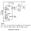
You can make a simple 2-transistors multivibrator oscillator or use an oscillator IC like this one:
 

Attachments

  • oscillator for inverter.png
    oscillator for inverter.png
    66.7 KB · Views: 10
thanks audio guru. was looking at ic's for this as I want it to go high frequency. still looking at whats best
 
You did not say the high frequency number.
The Mosfets you want to drive have a high gate-source input capacitance that takes a fairly high current for the Mosfets to work at a high frequency. The CD4047 output current is not high enough, buffers are needed to boost the output currents of the CD4047 to drive Mosfets at high frequencies.
 
Top