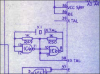
A crystal between XTAL and EXTAl uses the internal oscillator of the chip.
In this circuit teh NAND gates ar euses as Inverters (both inputs connected) and the inverters are biased to linear operation by the feedback resistors R49 and R50 (this is an abuse of CMOS inverters seen not seldom). These amplifiers and teh crystal in the overall feedback loop form the oscillator as
described here. The output from IC6, pin 11 is used to clock the MCU.