Maker Pro
Maker Pro

More efficient LDR "dark" switch?

Can anyone assist me with making a LDR switch? I specifically need a high efficiency and inexpensive setup since the intended circuit will run off of one 2032 battery. The switched circuit will consist of two small led's and a very low draw IC.

The switch as pictured below gets switched on when the LDR goes dark and off when there is sufficient ambient light. The 10k pot will allow for some adjustment to the light intensity cutoff, but may be omitted in future circuit if a specific value can be found by trial and error.

My existing setup shown below consumes 0.12mA while in standby - i.e. while its bright and the switched circuit is held in off state - about 78 days in standby until the battery is drained (assuming a 2032 has 225mAh).

upload_2015-6-15_1-10-31.png
 

Harald Kapp

Moderator
Moderator
The disadvantage of this circuit is that it will always require a comparatively high current:
  • When it is bright, R3 has a low resistance and current will flow to ground through R3.
  • When it is dark, R3 has a high resistance and current will flow to ground through the transistor.
Ideally your circuit would use current only when it is dark (because then the attached load will be powered anyway).
In addition your circuit would use a Schmitt-Trigger characteristic to generate a clean on or off signal at dusk and dawn.
Here is a sample circuit (note: use the CMOS version of the 555 for low power). Since in this setup the voltage at the output of the voltage divider (LDR+poteniometer) is the controlling factor, not the current through the resistors, you can reduce power consumption by adding series resistors to each of LDR and potentiometer, thus increasing total resistance of the voltage divider.
 
The circuits above are very inefficient.

How much current do you want to source?

In general, a Darlington can be used and it will consume about 3-10uA.
 
Since in this setup the voltage at the output of the voltage divider (LDR+poteniometer) is the controlling factor, not the current through the resistors, you can reduce power consumption by adding series resistors to each of LDR and potentiometer, thus increasing total resistance of the voltage divider.

Good solution, just increase the overall resistance of the voltage divider on both sides (no net effect on the triggering properties). So I could increase the resistance of the 22k resistor and add the same amount to the LDR. I will give that a go, thanks!

@Harald Kapp - Well I gave it a go, but no success. For some reason the switched load stays lit as soon as I install the last resistor. I used 220k for each series resistor, one for the pot and one for the LDR and tapped a lead from between to bring to the 6.7k resistor to the transistor base. In theory I understood why it should work, we are only increasing the total resistance such that less current flows, the voltage divider would stay intact as both sides would be equivalent as to their originals in proportion.

Edit - I used the 220k resistors in series with my original circuit, not Haralds.
 
Last edited:
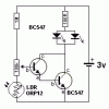
Here is a suitable circuit:
View attachment 20506
Unfortunately, I tried this circuit with two 2n2222, (closest thing I have on hand to the bc547) without any success. I measured to see if there was any current at the second transistor base and there was none. Is it possible that there is simply not enough current being passed to the first (leftmost) transistor to open the gate? The first base is split between the resistance of the LDR and the 1M resistor with the 100k pot being the tie point (a voltage divider circuit)
 
Perhaps overkill... but what about this?
http://ww1.microchip.com/downloads/en/DeviceDoc/30009941F.pdf
PIC microcontrollers have some intense low power features.
Hook up an LDR, and an LDR. Wake the PIC up every once in a while, power the LDR Voltage divider and get a reading on it. If it's still light, turn off power to the LDR voltage divider and sleep again.
If it's dark, turn on the LED ;)

You can increase battery life by increasing the time the pic stays in sleep between checking the sensor. this will make the light less responsive if you start waiting too long, but the result will be longer battery life with only a 10-20 nA of current during sleep .

I love it, but in this case I am trying to stay strictly analog. My programming skills and deciphering of the PIC registers is not quite there yet. If I must stay at 0.125mA on standby, I guess I can live with it, I was just trying to eek out a little more efficiency and thought transistor as switches were the answer.
 

hevans1944

Hop - AC8NS
Colin's circuit should have worked with the BC547 transistors. See attached datasheet. The 2N2222 is a small-signal, higher-current transistor, whose gain increases significantly with increasing collector current, but you need gain at reduced collector current. See attached datasheet. If you want to substitute for the BC547, I recommend the 2N3904, see also attached datasheet. OTH, the circuit does not provide any hysteresis as the CMOS 555 would that @Harald Kapp suggested. I don't understand why that didn't work for you. Did you try it with a CMOS version of the NE555 timer chip? You could use both circuits. The collector of the second transistor in Colin's circuit should, at some level of low light-level illumination on the LDR, move from saturation into a less conductive state. You can connect this in place of the LDR on the 555 circuit to obtain hysteresis, although the setpoint might get a little sensitive and difficult to adjust.

Can you measure the LDR resistance under the low light-level conditions where you want the output to change state?
 

Attachments

  • PN2222A.pdf
    191.8 KB · Views: 92
  • 2N3904.pdf
    426.9 KB · Views: 93
  • BC547.pdf
    192.7 KB · Views: 100
Last edited:
I misread Harald's initial advice, I thought he was stating that I could simply increase my resistance in both halves of the divider thereby lowering how much current would pass through to the rest of the circuit. I thought that this was good advice and would save some energy, but in practice I think the increased resistance prevented the circuit from working at all. I didn't realize that he was saying I should use the linked circuit.

I am trying to keep my part count to a bare minimum and only analog, no PIC's ;-)

The LDR measures 180Ω in bright light, 150k in a dark room and 1MΩ pitch black (almost). Somewhere around 150k would be ideal - of course I can use a trimpot to adjust as necessary.
 

hevans1944

Hop - AC8NS
I currently have a house full of grandchildren running around, helter-skelter, here in Virginia Beach. When (if) things settle down, I will try to work on your problem. Realistically, that may not be until after I return to Dayton... <sigh> Plus, it was in the high 90s today (felt more like over 100F when I ventured outside for a trip to Wally-World to buy groceries), and the A/C here in the house is NOT keeping up. Temps in Dayton were in the low 70s to mid 80s. <double sigh>
 
Top